NA v1.1.4: Difference between revisions
Jump to navigation
Jump to search
| Line 20: | Line 20: | ||
= Diagrams = | = Diagrams = | ||
== Circuit == | |||
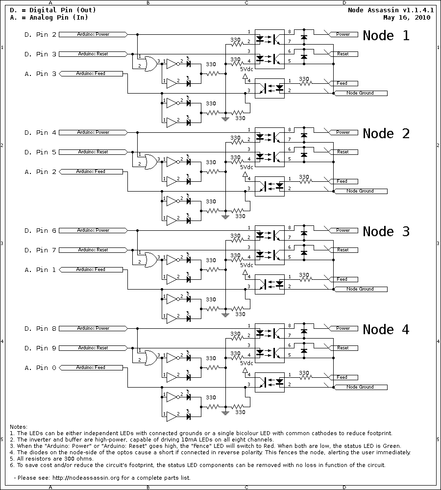
[[Image:na_v1.1.4_circuit_diagram.png|thumb|900px|center|Circuit diagram for the four-port Node Assassin v1.1.4.]] | [[Image:na_v1.1.4_circuit_diagram.png|thumb|900px|center|Circuit diagram for the four-port Node Assassin v1.1.4.]] | ||
== PADS-4 Layout == | |||
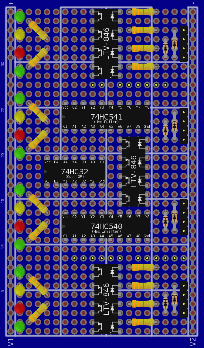
This is an "in progress" view of the board. Final layout and wiring are still needed. | |||
[[Image:na_v1.1.4_full_build_01.png|thumb|672px|center|Board Layout preview using the PADS-4 prototyping board. Wiring and final layout still to come.]] | |||
{{na_footer}} | {{na_footer}} | ||
Revision as of 03:38, 27 March 2010
|
Node Assassin :: NA v1.1.4 |
This version of the Node Assassin hardware implements an 8-bit bus to get the internal port count up high to support 3 channels per node (power button, reset button and power source).
Part List
- 1x Arduino: Duemilanova
- 1x Network Shield: Assembled
- 1x Protoboard: Lab-Easy PADS-4 (or equivalent)
- 3x Optoisolators: LTV-846 (4 circuits/chip)
- 1x Inverter: 74HC540 (8-channel high-power; drives 8x 10mA LED)
- 1x Buffer: 74HC541 (8-channel high-power; drives 8x 10mA LED)
- 1x OR-Gate: 74HC32 (Quad OR Gate)
- 8x Diode: 1N4148 (Diode)
Either:
- 4x Green LEDs (max 10mA)
- 4x Red LEDs (max 10mA)
OR (harder to find)
- 4x Bicolour LEDs: 350-1839-ND (Bicolour Red/Green, 2x1 stack, common cathode, max 10mA/colour)
Diagrams
Circuit

PADS-4 Layout
This is an "in progress" view of the board. Final layout and wiring are still needed.

| Input, advice, complaints and meanderings all welcome! | ||||
| Digimer | digimer@alteeve.ca | https://alteeve.ca/w | legal stuff: | |
| All info is provided "As-Is". Do not use anything here unless you are willing and able to take resposibility for your own actions. © 1997-2013 | ||||
| Naming credits go to Christopher Olah! | ||||
| In memory of Kettle, Tonia, Josh, Leah and Harvey. In special memory of Hannah, Jack and Riley. | ||||