Unused files
Jump to navigation
Jump to search
The following files exist but are not embedded in any page. Please note that other web sites may link to a file with a direct URL, and so may still be listed here despite being in active use.
Showing below up to 104 results in range #21 to #124.
-
 Na v1.1.4 full build 02.png 680 × 1,360; 436 KB
-
 An Opeongo island 01.jpg 2,288 × 1,712; 799 KB
-
 Our Opeongo island 01.jpg 2,288 × 1,712; 758 KB
-
 Our Opeongo island 02.jpg 2,288 × 1,712; 845 KB
-
 Our Opeongo island 03.jpg 2,288 × 1,712; 770 KB
-
 Our Opeongo island 04.jpg 2,288 × 1,712; 887 KB
-
 Our Opeongo island 05.jpg 2,288 × 1,712; 802 KB
-
 Our Opeongo island 07.jpg 2,288 × 1,712; 742 KB
-
 Our Opeongo island 06.jpg 2,288 × 1,712; 911 KB
-
 Our Opeongo island 08.jpg 2,288 × 1,712; 776 KB
-
 Our Opeongo island 09.jpg 2,288 × 1,712; 716 KB
-
 Alteeve server 01.jpg 2,592 × 1,944; 912 KB
-
 2-pin bicolour LED circuit try1.png 349 × 103; 2 KB
-
 Virt-manager local-node 01.png 586 × 442; 166 KB
-
 Virt-manager local-node 02.png 736 × 670; 123 KB
-
 Virt-manager remote-workstation 01.png 972 × 577; 65 KB
-
 Virt-manager remote-workstation 02.png 562 × 577; 38 KB
-
 F13 httpd default page 01.png 1,036 × 795; 147 KB
-
 Node Assassin v1.2.0 inverted 01-Board Prep.png 1,980 × 1,060; 221 KB
-
 Node Assassin v1.2.0 04-Ground Lines.png 1,980 × 1,060; 547 KB
-
 Node Assassin v1.2.0 05-Node Grounds.png 1,980 × 1,060; 585 KB
-
 Node Assassin v1.2.0 06-Node Power Feeds.png 1,980 × 1,060; 565 KB
-
 Node Assassin v1.2.0 09-Cable Detect In.png 1,980 × 1,060; 475 KB
-
 Node Assassin v1.2.0 10-Node Feed Opto Via Buffer To Input.png 1,980 × 1,060; 494 KB
-
 Node Assassin v1.2.0 11-Buffer To Inverters.png 1,980 × 1,060; 417 KB
-
 Node Assassin v1.2.0 12-Output To Opto Anode.png 1,980 × 1,060; 651 KB
-
 Node Assassin v1.2.0 13-Opto Anode To OR.png 1,980 × 1,060; 526 KB
-
 Node Assassin v1.2.0 14-OR To Inverter.png 1,980 × 1,060; 458 KB
-
 Node Assassin v1.2.0 15-OR To Fenced LED.png 1,980 × 1,060; 469 KB
-
 Node Assassin v1.2.0 16-Inverter To Fence OK LED.png 1,980 × 1,060; 496 KB
-
 Node Assassin v1.2.0 18-Buffer To Node On LED.png 1,980 × 1,060; 521 KB
-
 Node Assassin v1.2.0 inverted 02-Part Placement.png 1,980 × 1,060; 117 KB
-
 Node Assassin v1.2.0 inverted 04-Ground Lines.png 1,980 × 1,060; 300 KB
-
 Node Assassin v1.2.0 inverted 05-Node Grounds.png 1,980 × 1,060; 334 KB
-
 Node Assassin v1.2.0 inverted 06-Node Power Feeds.png 1,980 × 1,060; 314 KB
-
 Node Assassin v1.2.0 inverted 09-Cable Detect In.png 1,980 × 1,060; 227 KB
-
 Node Assassin v1.2.0 inverted 10-Node Feed Opto Via Buffer To Input.png 1,980 × 1,060; 238 KB
-
 Node Assassin v1.2.0 inverted 11-Buffer To Inverters.png 1,980 × 1,060; 166 KB
-
 Node Assassin v1.2.0 inverted 12-Output To Opto Anode.png 1,980 × 1,060; 415 KB
-
 Node Assassin v1.2.0 inverted 13-Opto Anode To OR.png 1,980 × 1,060; 273 KB
-
 Node Assassin v1.2.0 inverted 14-OR To Inverter.png 1,980 × 1,060; 208 KB
-
 Node Assassin v1.2.0 inverted 15-OR To Fenced LED.png 1,980 × 1,060; 208 KB
-
 Node Assassin v1.2.0 inverted 16-Inverter To Fence OK LED.png 1,980 × 1,060; 239 KB
-
 Node Assassin v1.2.0 inverted 18-Buffer To Node On LED.png 1,980 × 1,060; 278 KB
-
 Node Assassin v1.2.0 17-Inverter To Node Off LED.png 1,980 × 1,060; 481 KB
-
 Node Assassin v1.2.0 inverted 17-Inverter To Node Off LED.png 1,980 × 1,060; 227 KB
-
 Node Assassin v1.2.0 inverted 03-Power Lines.png 1,980 × 1,060; 200 KB
-
 Node Assassin v1.2.0 03-Power Lines.png 1,980 × 1,060; 446 KB
-
 Node Assassin v1.2.0 inverted 07-Node Reset Lines.png 1,980 × 1,060; 208 KB
-
 Node Assassin v1.2.0 07-Node Reset Lines.png 1,980 × 1,060; 484 KB
-
 Node Assassin v1.2.0 08-Node Power Lines.png 1,980 × 1,060; 556 KB
-
 Node Assassin v1.2.0 inverted 08-Node Power Lines.png 1,980 × 1,060; 313 KB
-
 Node Assassin v1.2.0 01-Board Prep.png 1,980 × 1,060; 425 KB
-
 Node Assassin v1.2.0 02-Part Placement.png 1,980 × 1,060; 372 KB
-
 Na v1.2.0 circuit diagram.png 820 × 440; 71 KB
-
 Xen vm0001 fw1 install 01.png 1,440 × 900; 471 KB
-
 Live migration vm0002 win7 to an-node02 ping.png 1,440 × 900; 234 KB
-
 Starting the vm node 01.png 1,440 × 900; 801 KB
-
 Verifying storage shutdown 01.png 1,440 × 900; 752 KB
-
 Stopping the cman daemon 01.png 1,440 × 900; 792 KB
-
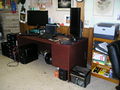 Madi desktop machines.jpg 2,288 × 1,712; 743 KB
-
 2-node el6-tutorial network-test 01.png 2,640 × 1,920; 983 KB
-
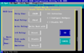
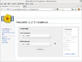 Mw config 01.png 887 × 664; 86 KB
-
 Mw config 02.png 1,440 × 900; 162 KB
-
 Mw config 04.png 1,440 × 900; 113 KB
-
 2n-RHEL6-KVM vm0002 provision 01.png 1,440 × 900; 498 KB
-
 2n-RHEL6-KVM vm0002 provision 02.png 1,440 × 900; 272 KB
-
 2n-RHEL6-KVM vm0002 provision 03.png 1,440 × 900; 287 KB
-
 2n-RHEL6-KVM vm0002 provision 04.png 1,440 × 900; 276 KB
-
 2n-RHEL6-KVM vm0002 provision 05.png 1,440 × 900; 272 KB
-
 2n-RHEL6-KVM vm0002 provision 06.png 1,440 × 900; 192 KB
-
 2n-RHEL6-KVM vm0002 eject-media 01.png 1,440 × 900; 133 KB
-
 2n-RHEL6-KVM vm0002 eject-media 02.png 1,440 × 900; 121 KB
-
 2n-RHEL6-KVM vm0002 eject-media 03.png 1,440 × 900; 98 KB
-
 2n-RHEL6-KVM vm0002 eject-media 04.png 1,440 × 900; 95 KB
-
 2n-RHEL6-KVM vm0002 eject-media 05.png 1,440 × 900; 100 KB
-
 2n-RHEL6-KVM vm0002 eject-media 06.png 1,440 × 900; 96 KB
-
 2n-RHEL6-KVM vm0002 eject-media 07.png 1,440 × 900; 102 KB
-
 AN-Labs 1.jpg 2,592 × 1,944; 902 KB
-
 AN-Labs 2.jpg 2,592 × 1,944; 881 KB
-
 Vm0001-dev ping-flood live-migration-test 01.png 1,440 × 900; 63 KB
-
 Striker first-connect.png 1,480 × 1,053; 41 KB
-
 Striker new-dashboard.png 1,480 × 1,053; 64 KB
-
 Striker initial-global-variable-form.png 1,480 × 1,053; 158 KB
-
 Striker updating-initial-global-variables.png 1,480 × 1,053; 159 KB
-
 Striker saving-changes-to-global-variables.png 1,480 × 1,053; 74 KB
-
 Striker click-on-new-anvil-button.png 1,480 × 1,053; 155 KB
-
 Striker configure-first-anvil.png 1,480 × 1,053; 226 KB
-
 Striker saving-first-anvil.png 1,480 × 1,053; 205 KB
-
 Striker first-anvil-saved.png 1,480 × 1,053; 63 KB
-
 Striker editing-first-anvil.png 1,480 × 1,053; 224 KB
-
 Striker first-anvil-added.png 1,480 × 1,053; 63 KB
-
 Striker main-page-with-new-anvil.png 1,480 × 1,053; 165 KB
-
 Striker connecting-to-the-new-anvil.png 1,480 × 1,053; 201 KB
-
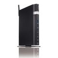 ASUS EeeBox PX1035.jpg 500 × 500; 12 KB
-
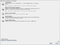 Striker-Install RHEL6-Install Partition 01.png 1,026 × 770; 55 KB
-
 France Flag.png 125 × 83; 307 bytes
-
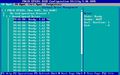 PRAID EP420i BIOS 01.jpeg 640 × 400; 54 KB
-
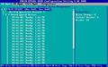 PRAID EP420i BIOS 01 Controller highlighted.jpeg 640 × 400; 54 KB
-
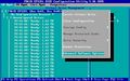 PRAID EP420i BIOS 01 Controller Operations.jpeg 640 × 400; 60 KB
-
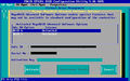 PRAID EP420i BIOS 01 Manage MegaRAID Advanced Software Options.jpeg 640 × 400; 69 KB
-
-
 French flag.png 900 × 600; 3 KB
-
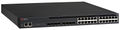 Brocade icx6610-24 iso 01.jpg 1,581 × 398; 144 KB


