File:Na v1.1.4 circuit diagram.png
Size of this preview: 540 × 600 pixels. Other resolution: 900 × 1,000 pixels.
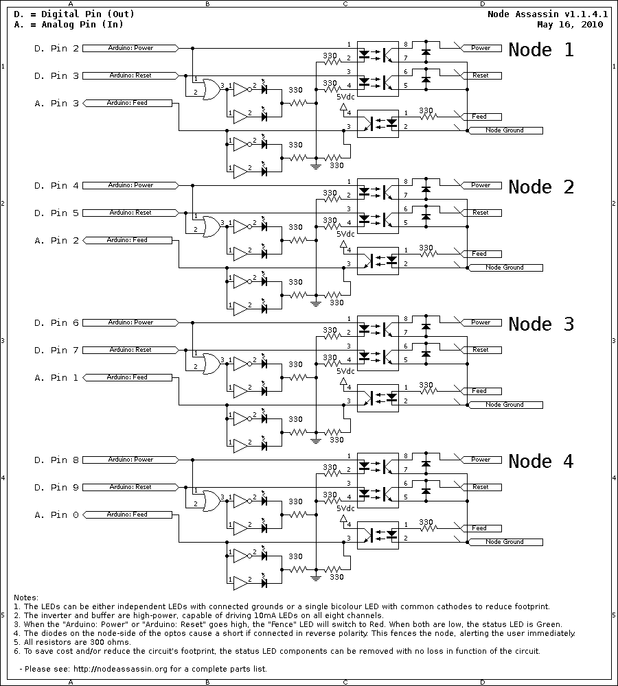
Original file (900 × 1,000 pixels, file size: 8 KB, MIME type: image/png)
Circuit diagram for one node of Node Assassin 1.1.4.
File history
Click on a date/time to view the file as it appeared at that time.
| Date/Time | Thumbnail | Dimensions | User | Comment | |
|---|---|---|---|---|---|
| current | 02:06, 17 May 2010 | | 900 × 1,000 (8 KB) | Digimer (talk | contribs) | Added the missing resistors on the arduino-side opto's cathodes. |
| 21:59, 15 May 2010 | 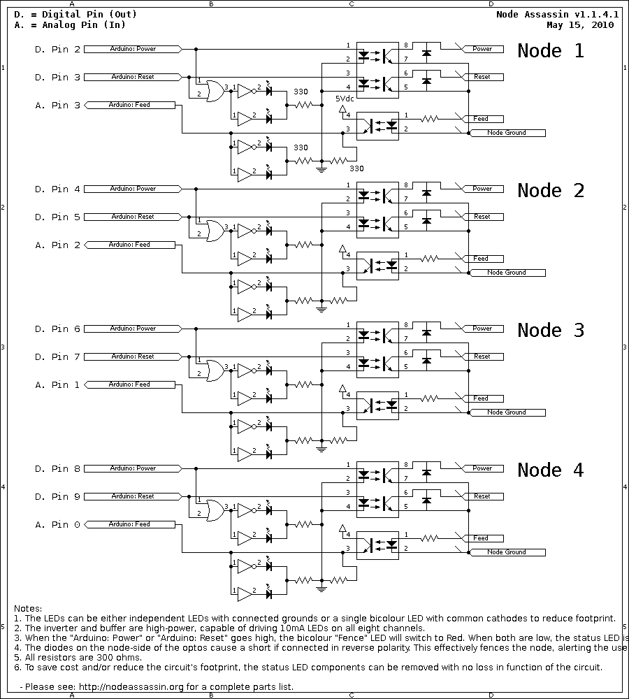 | 900 × 1,000 (9 KB) | Digimer (talk | contribs) | Updated to v1.1.4.1 - Added 330 ohm resistors to node power feed lines. | |
| 20:59, 16 April 2010 | 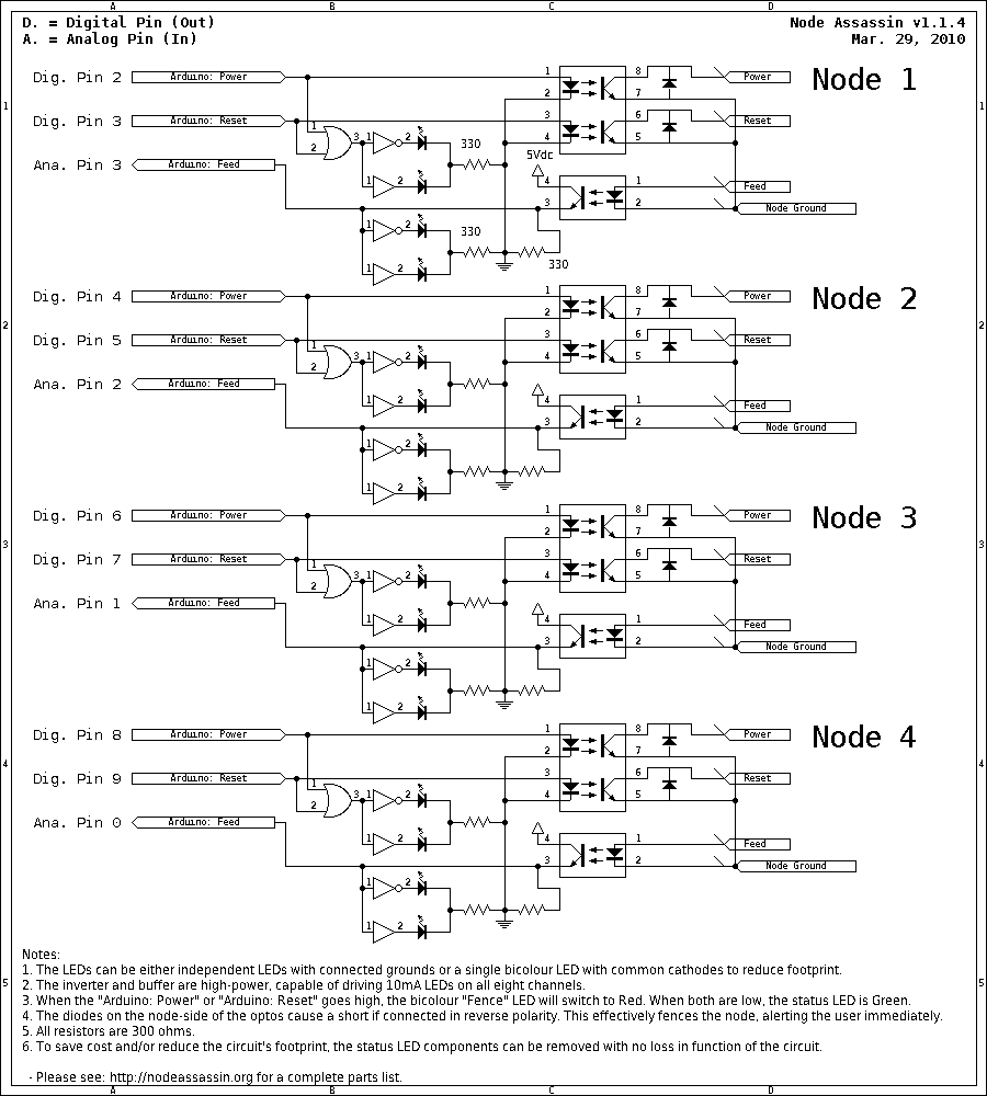 | 900 × 1,000 (8 KB) | Digimer (talk | contribs) | Made the "A." and "D." into "Ana." and "Dig." to clarify the differences in the pins numbers. | |
| 14:45, 29 March 2010 | 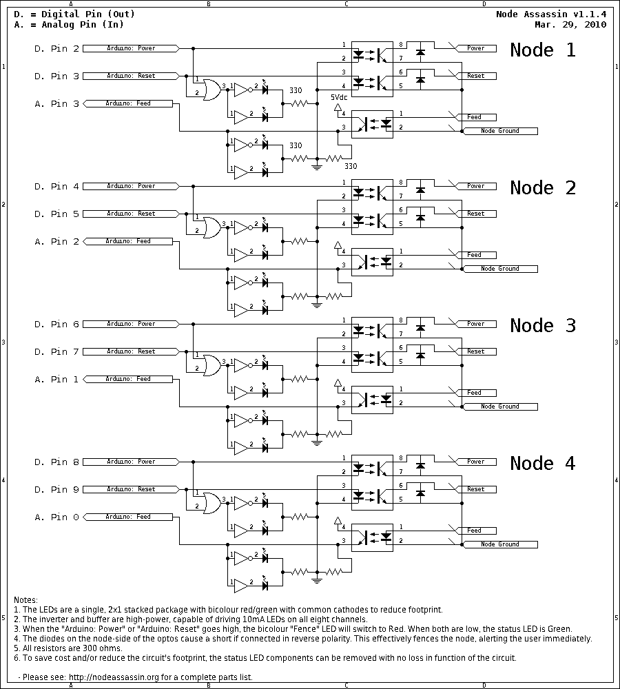 | 900 × 1,000 (8 KB) | Digimer (talk | contribs) | Updated the date to accurately reflect the diagram's update date. Date. | |
| 14:44, 29 March 2010 |  | 900 × 1,000 (8 KB) | Digimer (talk | contribs) | Added pull-down resistors to the Arduino input feeds and moved the power feed resistor to just resist the feed status LEDs. | |
| 04:24, 19 March 2010 | 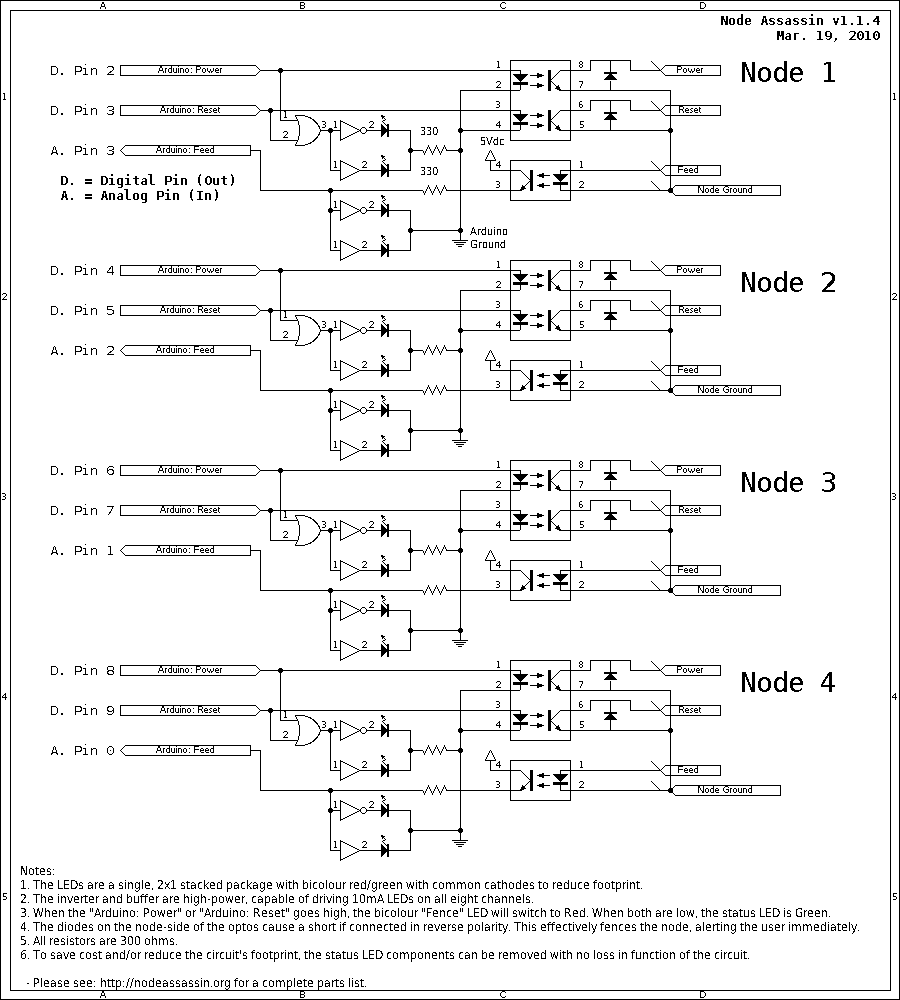 | 900 × 1,000 (9 KB) | Digimer (talk | contribs) | Circuit diagram for the four-port Node Assassin v1.1.4. | |
| 22:10, 7 March 2010 |  | 640 × 480 (7 KB) | Digimer (talk | contribs) | Circuit diagram for one node of Node Assassin 1.1.4. |
You cannot overwrite this file.
File usage
The following 2 pages use this file: