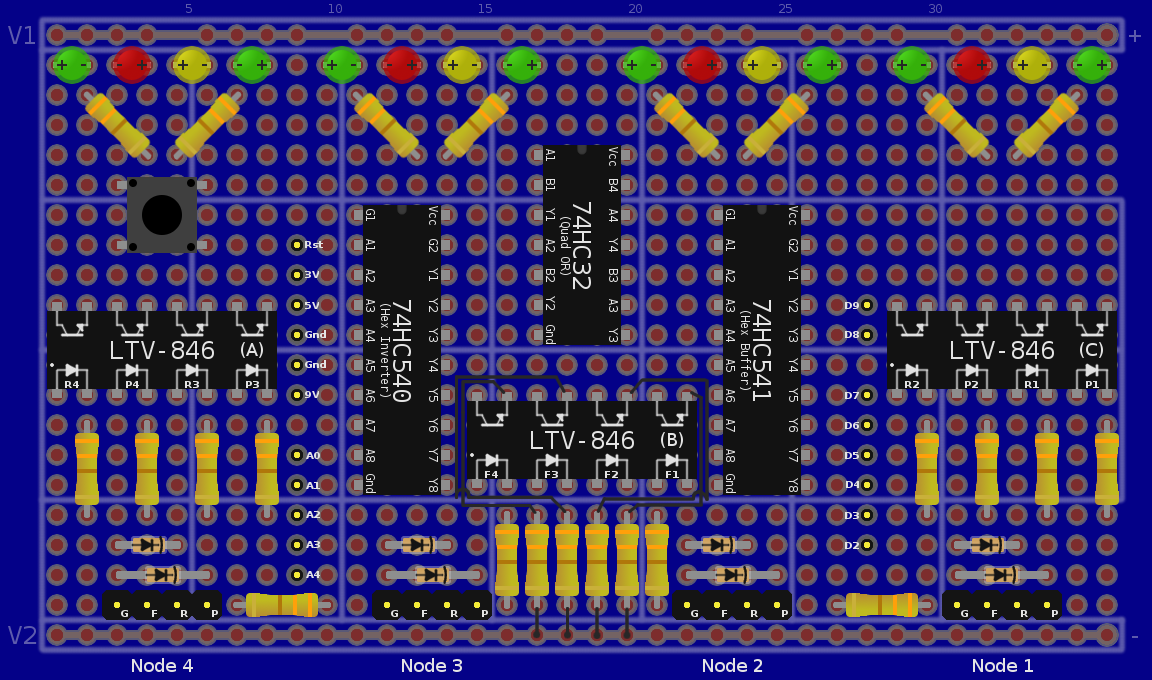
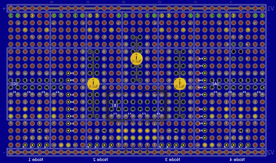
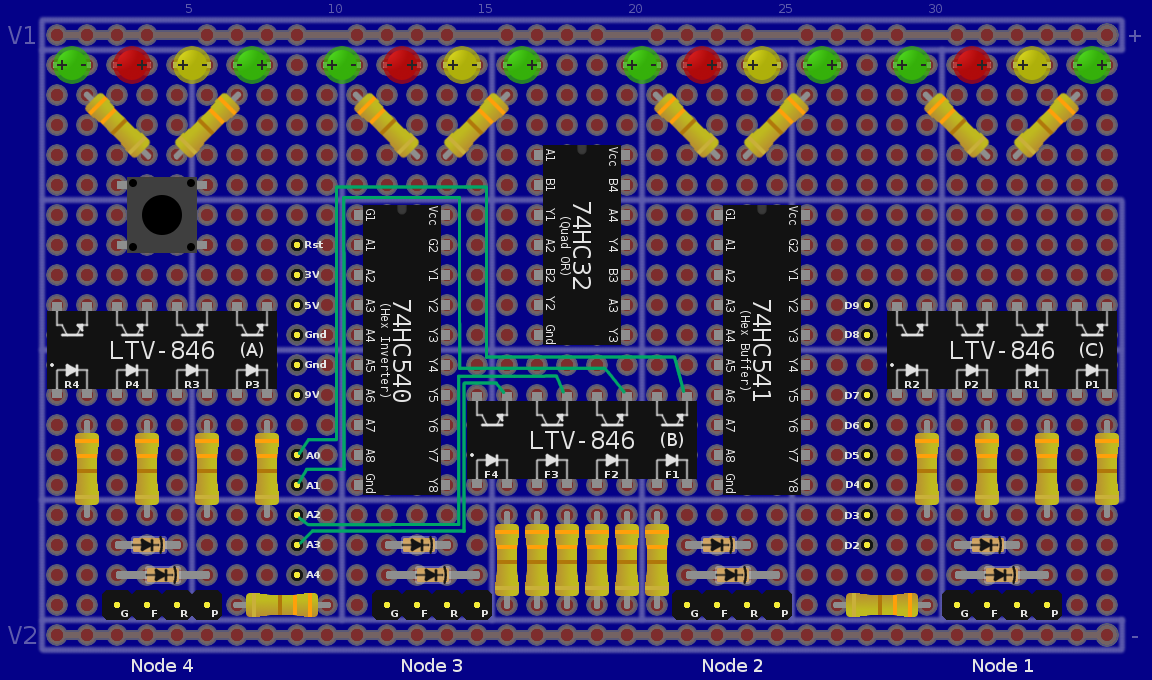
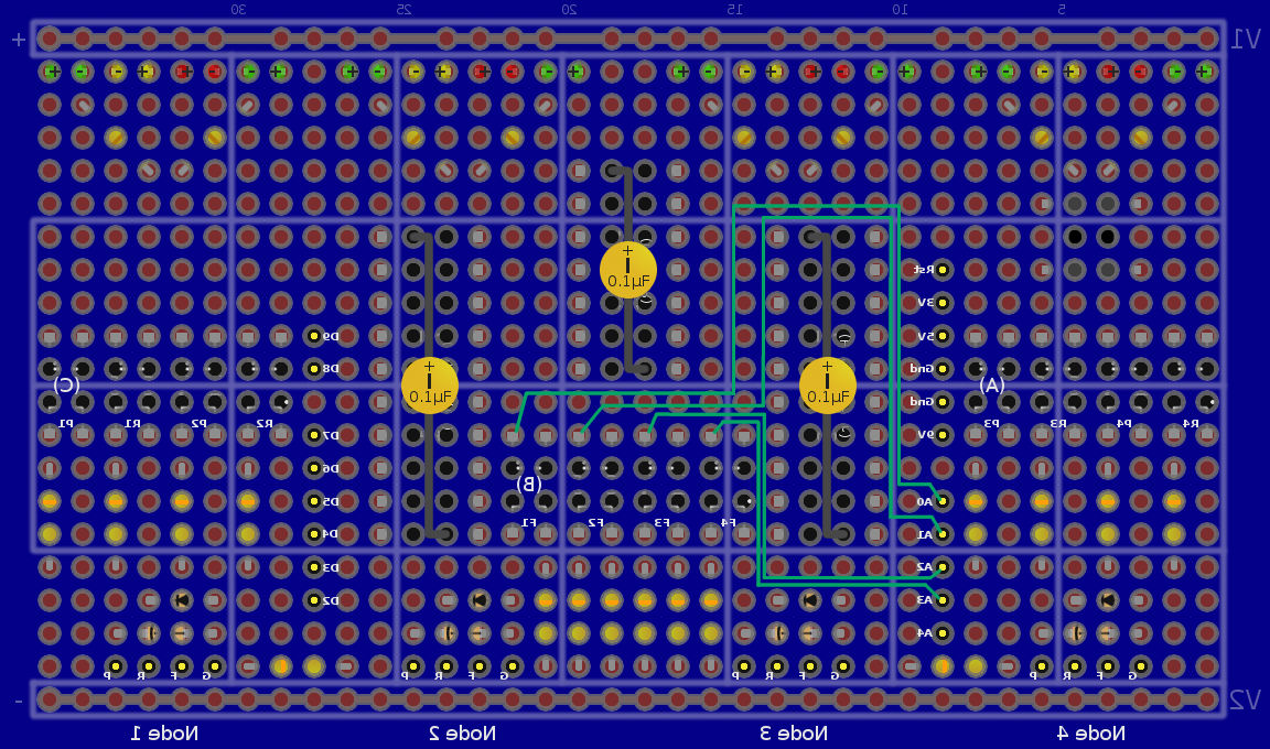
Building a Node Assassin v1.1.4
|
Node Assassin :: Node_Assassin v1.1.4 :: Building a Node Assassin v1.1.4 |

|
WARNING: This is a potentially risky project. If not built right, you may damage the device, your equipment or harm yourself. DO NOT follow these instruction or use anything on this website unless you are willing and able to assume all risk and liability. Alteeve's Niche! does it's best to mitigate risk and reduce the chances of ill effects, but does not guarantee this information to be free from defects, omissions and mistakes.
Now then, let's begin.
Updates
May 15, 2010: Updated the minor version to v1.1.4.1. This version adds 330ohm resistors to the node feed lines to make it safer to draw the signal directly from the PSU.
Overview

Building your own Node Assassin is relatively simple, but it will require a little patience and precision as there are a lot of joints that will need to be soldered. Some things to keep in mind:
- Before soldering each joint, be sure that you've accounted for all wires that are to go into that joint. Trying to solder in an additional wire after the joint is already made is tricky and increases the chance of damaging components and wires already soldered into the joint.
- Think about what order you want to solder in joints. Generally speaking, it is easier to start in the center of the board and then work outward. Add large components, like the extended length 2.54mm pitch pins, only when you need to so that they won't be in your way.
- Clean your solder tip after each joint.
- Use the minimal amount of solder needed to get a complete joint and apply the heat for the shortest time possible.
- Use a Helping Hand and a good light.
- Use a fan to suck the solder fumes away from you while working.
- Have a good pair of small needle nose pliers, edge cutters and wire strippers available. If you don't have a wire stripper small enough for wire-wrap wire, practice using your edge cutters to strip the wire.
- BE PATIENT! If this is your first project, you will make mistakes. That's ok, it's the best way to learn! Be sure to have some spare parts around in case you break something. Common parts to break when you are a beginner are resistors, LEDs (specially melting them), diodes and similar fine components. Getting frustrated will just cause you to ruin your project. Believe me, I speak from experience!
Parts List
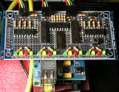 |
The Node Assassin itself is built to piggy-back on an Arduino and a network shield. If you already have these, you only need the parts for the Node Assassin itself. If not, then you will need to full kit. Any company that sells Arduino's will most likely carry all the other parts you will need. If you are having trouble sourcing the parts, we sell Node Assassin kits.
This is a complete parts list needed to build the 4-port Node Assassin described in the files in this directory. Many parts can be substituted if you are unable to find the exact part mentioned. If you replace a part, please ensure that it is electrically and mechanically compatible. |
Note: The example products linked below are not guaranteed to be accurate or appropriate. I need to spend a bit more time ensuring that parts are accurate still. Please verify before purchasing that the given part is compatible.
| Qty. | Description |
|---|---|
| 1 | Lab-Easy PADS-4 (or equiv) |
| 1 | 74HC32 (High Current Quad OR gate) |
| 1 | 74HC540 (High Current Hex Inverter) |
| 1 | 74HC541 (High Current Hex Buffer) |
| 3 | LTV-846 (Quad Optical Isolators) |
| 8 | 10mA (or lower) Green LEDs (example) |
| 4 | 10mA (or lower) Red LEDs (example) |
| 4 | 10mA (or lower) Yellow or Orange LEDs (example) |
| 24 | 330 ohm 0.25w resistors (example) |
| 3 | 0.1uF Capacitors (example) |
| 8 | 5V+ Zener Diode (example) |
| 40 | 2.54mm Pitch Board-to-Board Connectors, ~6mm connector length, solder type (4x4, 12x2) (example) |
| 20 | 2.54mm Pitch Board-to-Board Connectors, ~15mm connector length, solder type (3x6, 1x2) (example) |
| 1 | Micro Momentary Contact Switch (example) |
| 4 | 4-Position female 2.54mm pitch crimp connectors and housing (example housing, example mini-PV pin) |
| 12 | 2-Position female 2.54mm pitch crimp connectors and housing (example housing, example mini-PV pin) |
Wire lengths are suggested. In many cases you can use less, but the lengths recommended below provide healthy overhead. Colours are likewise adjustable. The colours mentioned are chosen to match with the diagrams provided.
Board Wiring: Please verify before purchasing that the given part is compatible.
| Length | Description |
|---|---|
| 6' | Black wire-wrap wire |
| 6' | Red wire-wrap wire |
| 6' | Green wire-wrap wire |
| 6' | Orange wire-wrap wire |
| 6' | Yellow wire-wrap wire |
Node Cables:
| Length | Description |
|---|---|
| 20' | Black 24awg Stranded Cable |
| 20' | Red 24awg Stranded Cable |
| 20' | Yellow 24awg Stranded Cable |
| 20' | Green 24awg Stranded Cable |
Node Cables
When creating the node cables, you may want to get a longer length of black wire as you will use extra to "fan out" from the node-end of the cable when connecting the two extra connectors.
Here is a block diagram of the wires you will need to make for each node:
[Node Assassin Side]                                            [Node Side]

                                        - ====||--------------\
 _____________                          + ====||------------\ |  _____________
|             |1                                            | | |             |
|======     + |--[Red - Power Button]-----~[4']~------------+-|-| +     ======|
|======     + |--[Yellow - Reset Button]--~[4']~----\   /-+-+-+-| -     ======|
|======     + |--[Green - Power Feed]-----~[4']~--\ |   | | |   |_____________|
|======     - |--[Black - Ground]---------~[4']~--|-|---/ | |    Power Button
|_____________|4                                  | |     | |
                                        - ====||--|-|-----|-+
                                        + ====||--|-+     | |    _____________
                                                  | |     | |   |             |
                                                  | \-----|-|---| +     ======|
                                                  |       | \---| -     ======|
                                                  |       |     |_____________|
                                                  |       |      Reset Button
                                                  |       |
                                        - ====||--|-------+
                                        + ====||--+       |      _____________
                                                  |       |     |             |
                                                  \-------|-----| +     ======|
                                                          \-----| -     ======|
                                                                |_____________|
                                                                 Power LED
You will need to make custom cables with pass through connectors to properly use Node Assassin. The only real requirement is that the connector attaching to the Node Assassin be 1x4 wide, 2.54 pitch female connector. Personally, I like to run a common ground to the power button connector and then fan it out to the other two connectors. Each distal connector needs to have a male pass-through connector so that you can still plug in the case cables.
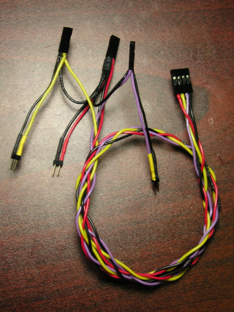 |
Note that if your motherboard uses the three-pin wide header for the power LED, just use a knife tip to swap out the connector on the NA cable with the chassis cable.
If you do not care about connecting the node's chassis' front panel connectors, you can forgo adding the somewhat tricky male pass-through pins.
Build Images
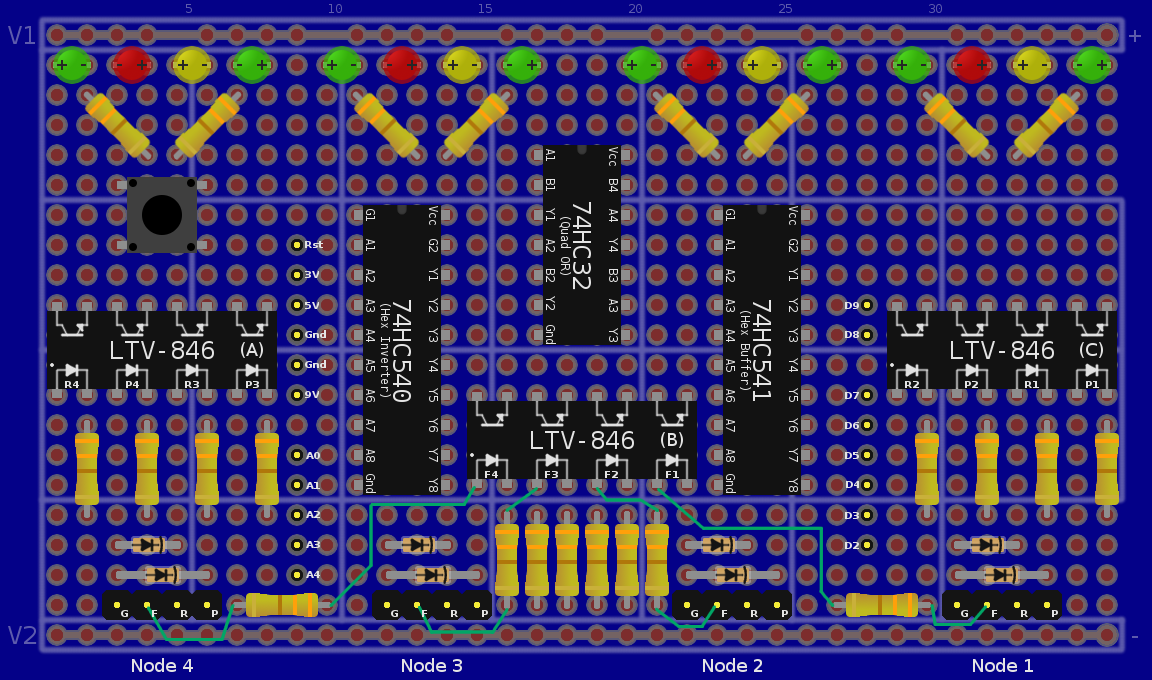
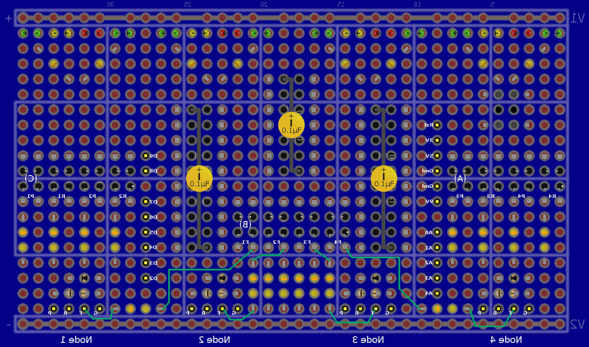
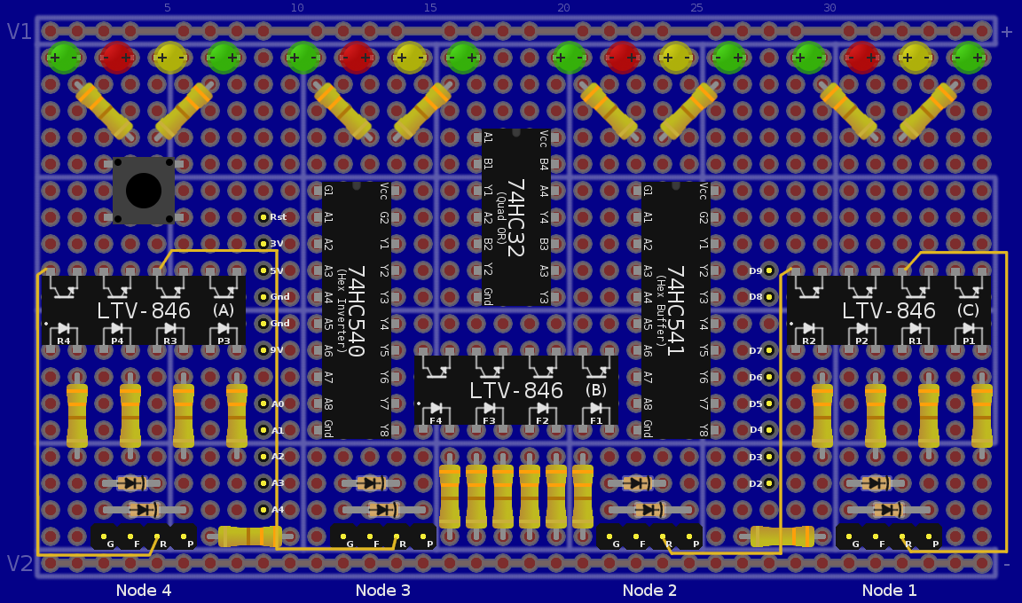
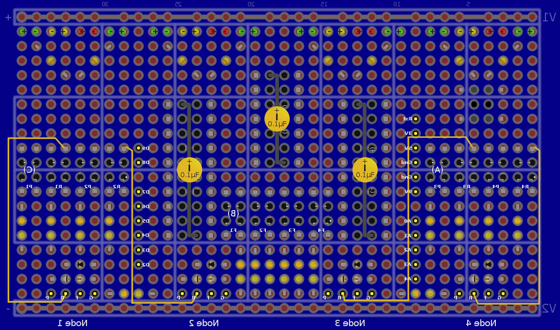
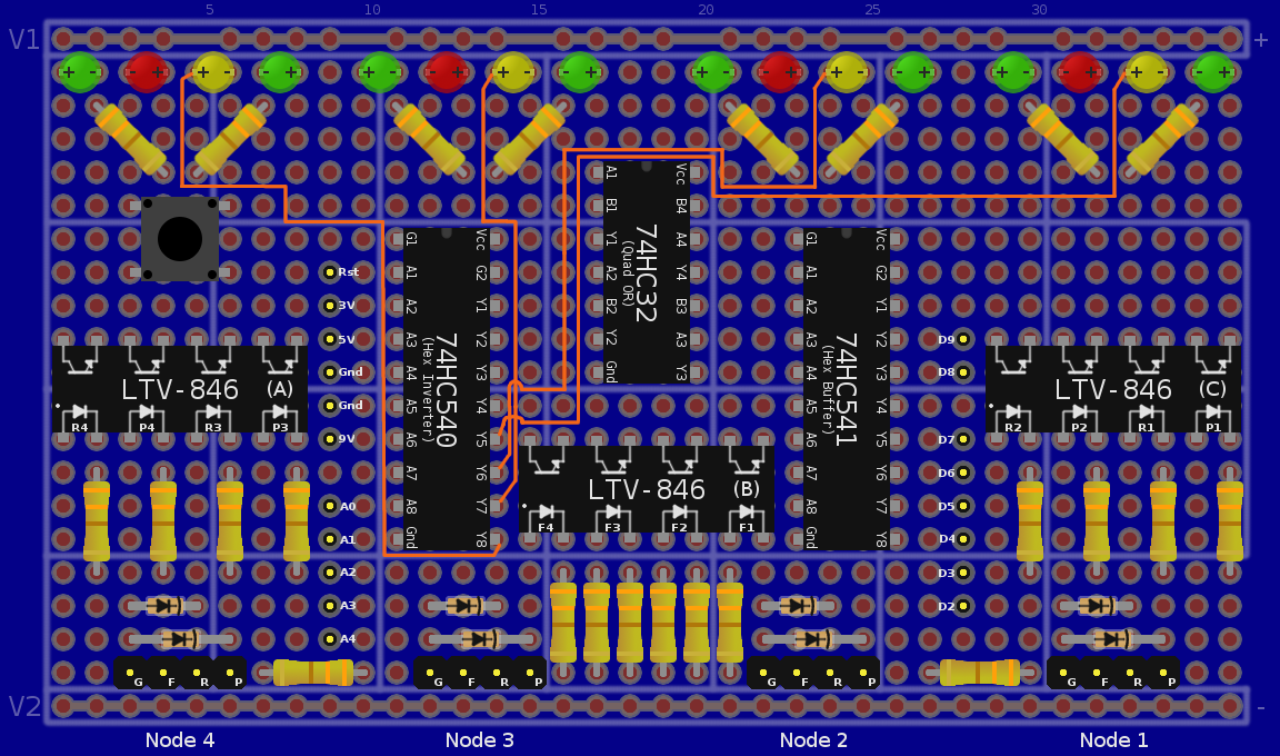
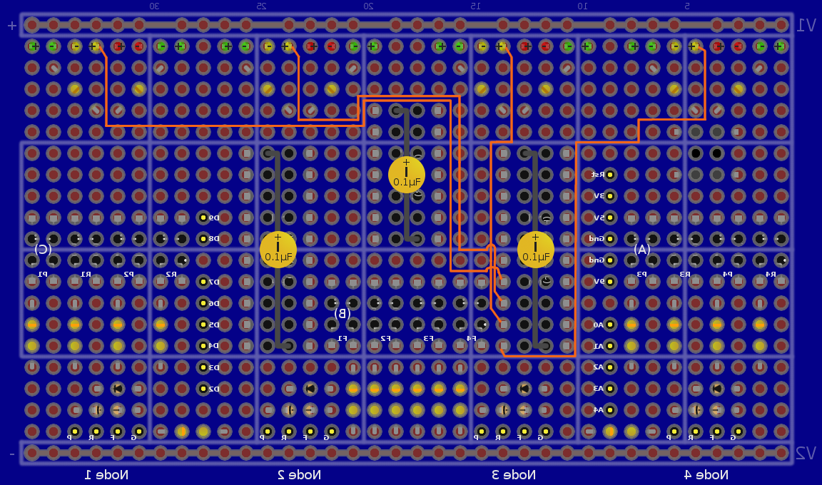
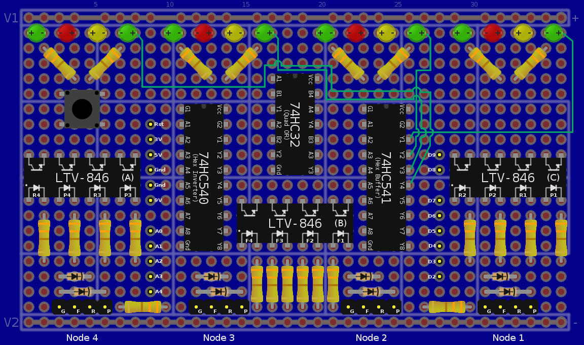
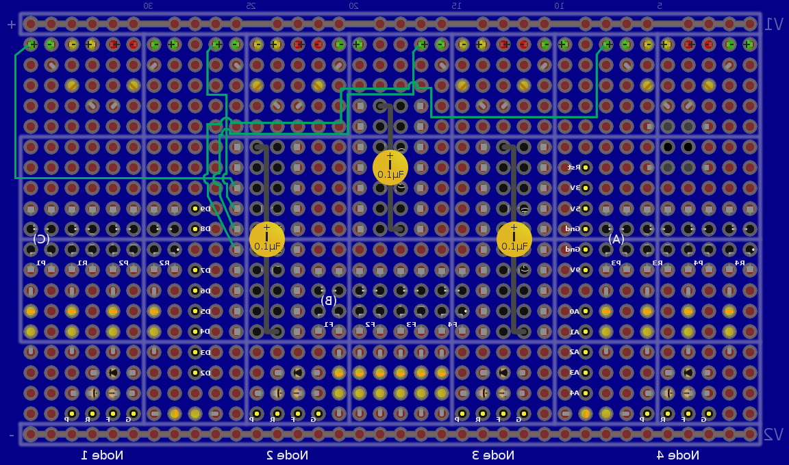
If you want to download all the images, XCF and ce3 files plus the BSchv3 program as one compressed file, click here:
- na_build_v1.1.4.1.tar.gz (updated on May 15, 2010 to add node power feed resistors)
I found it very useful to use an image viewer, like the free GeeQie, that could switch images via the mouse wheel. This allows you to rapidly compare different layers with the image of the board staying static on your screen.
Circuit Diagram
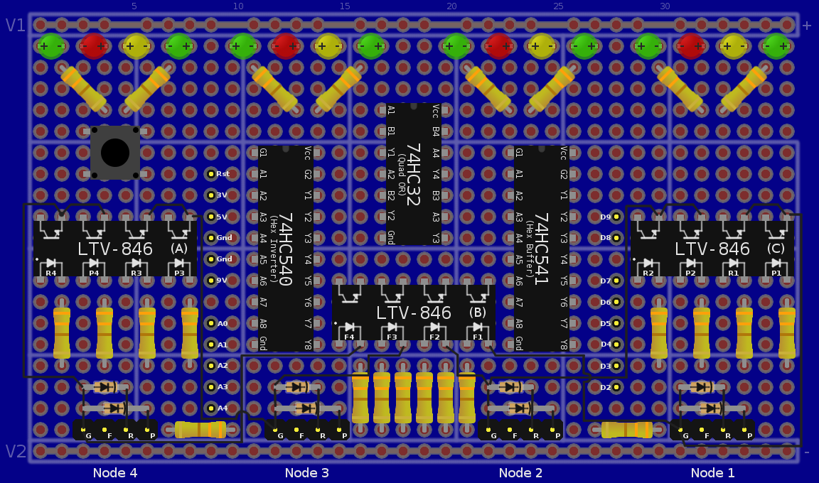
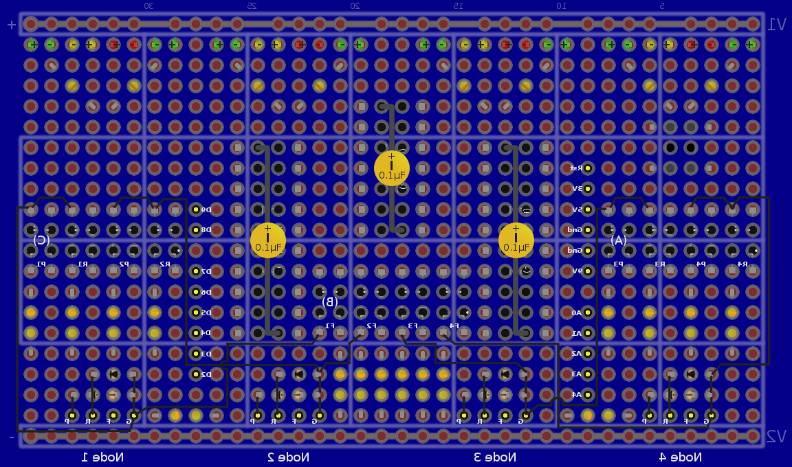
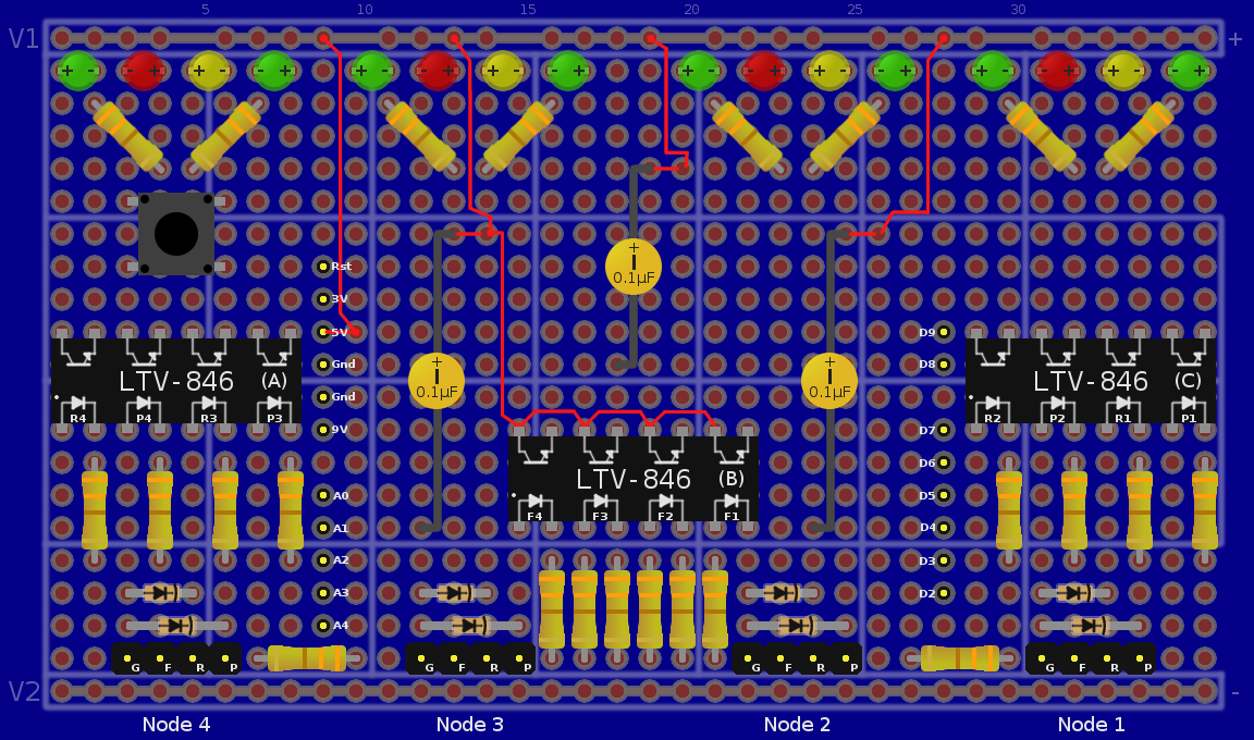
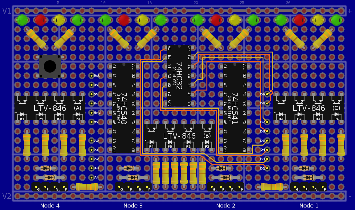
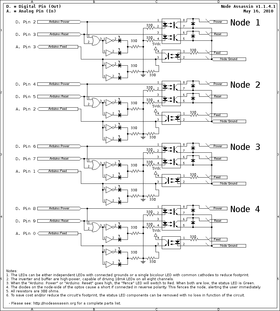
This is the BSchV3 generated circuit diagram for the v1.1.4.1 Node Assassin.
 |
Notice
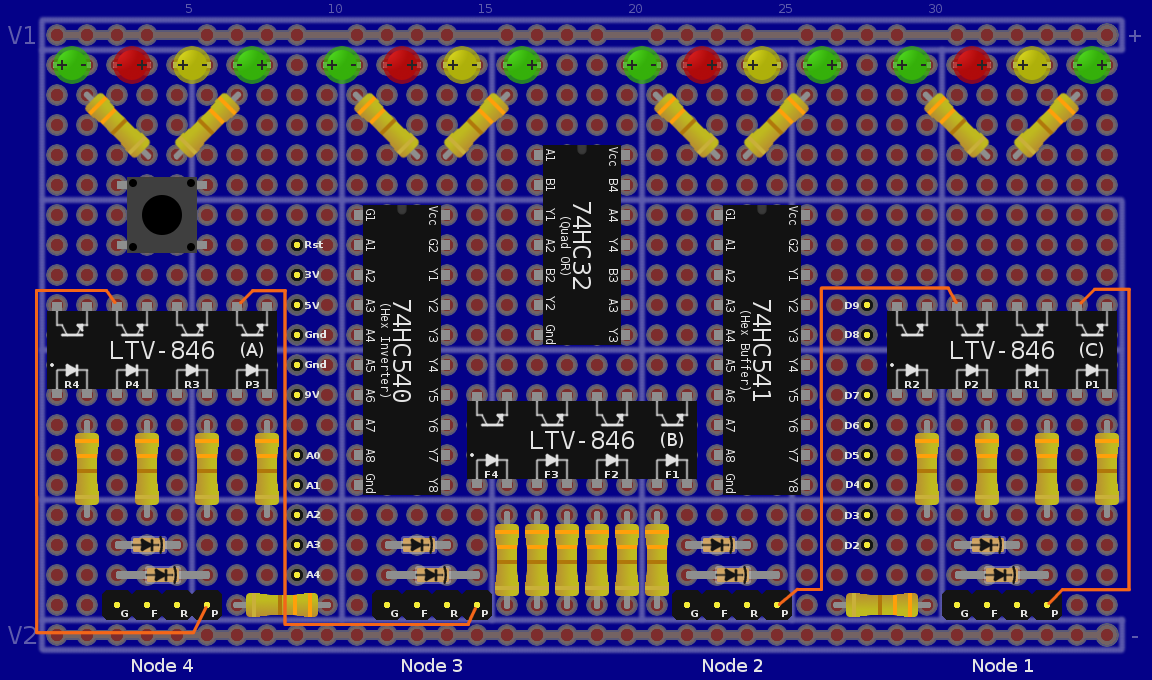
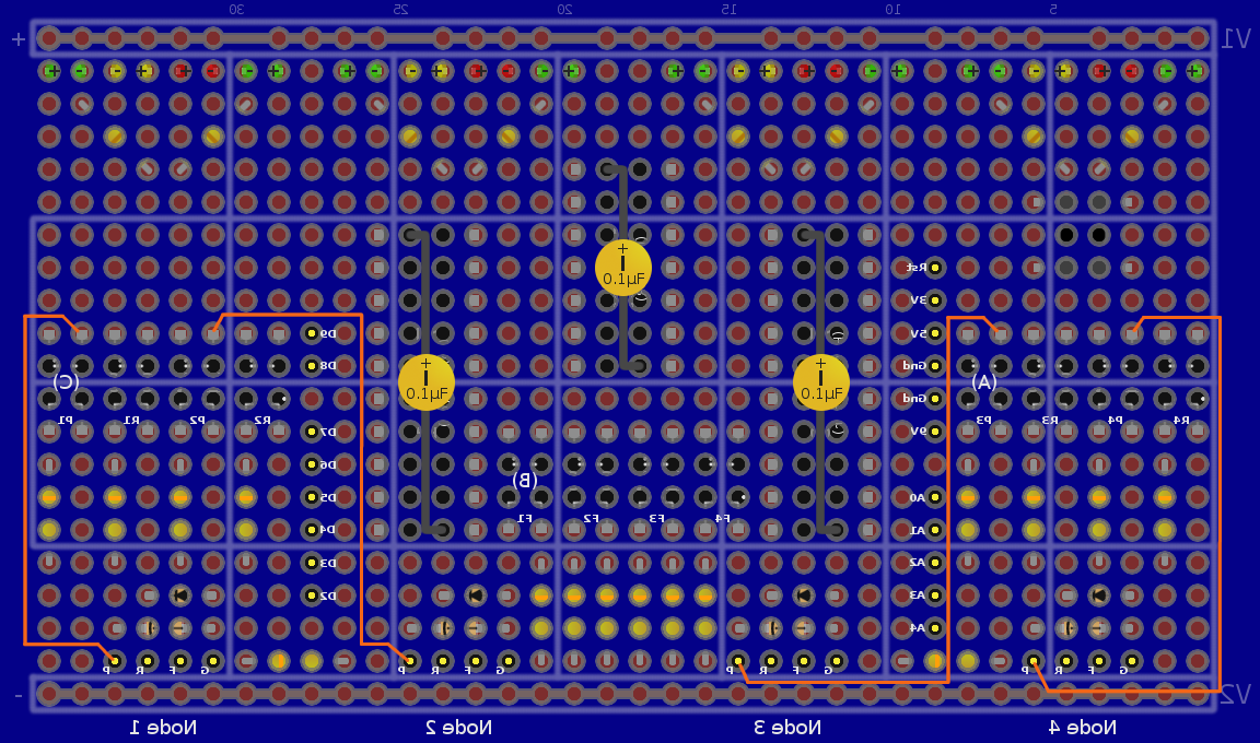
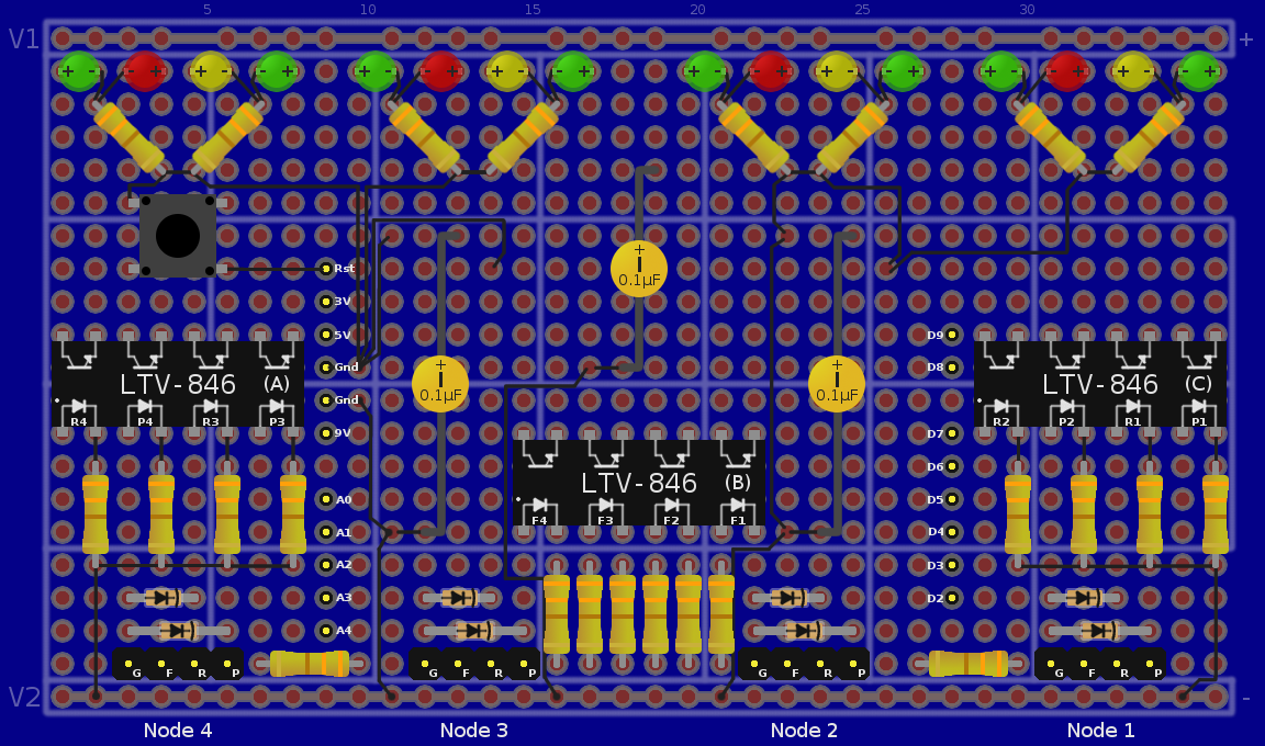
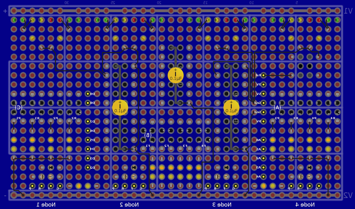
The following table is very wide and is best viewed on a wide screen display at high resolution. If you don't have a high-resolution monitor, you should be able to see each column in your screen at a time so long as your monitor's resolution is greater than 1,152 pixels wide (ie: 1280x800 or better). Simple use your browser's horizontal scroll bar to center on your screen the column you wish to follow.
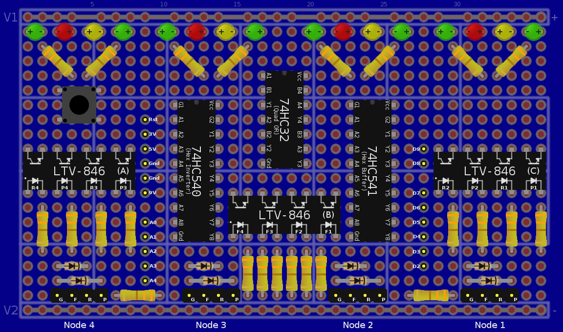
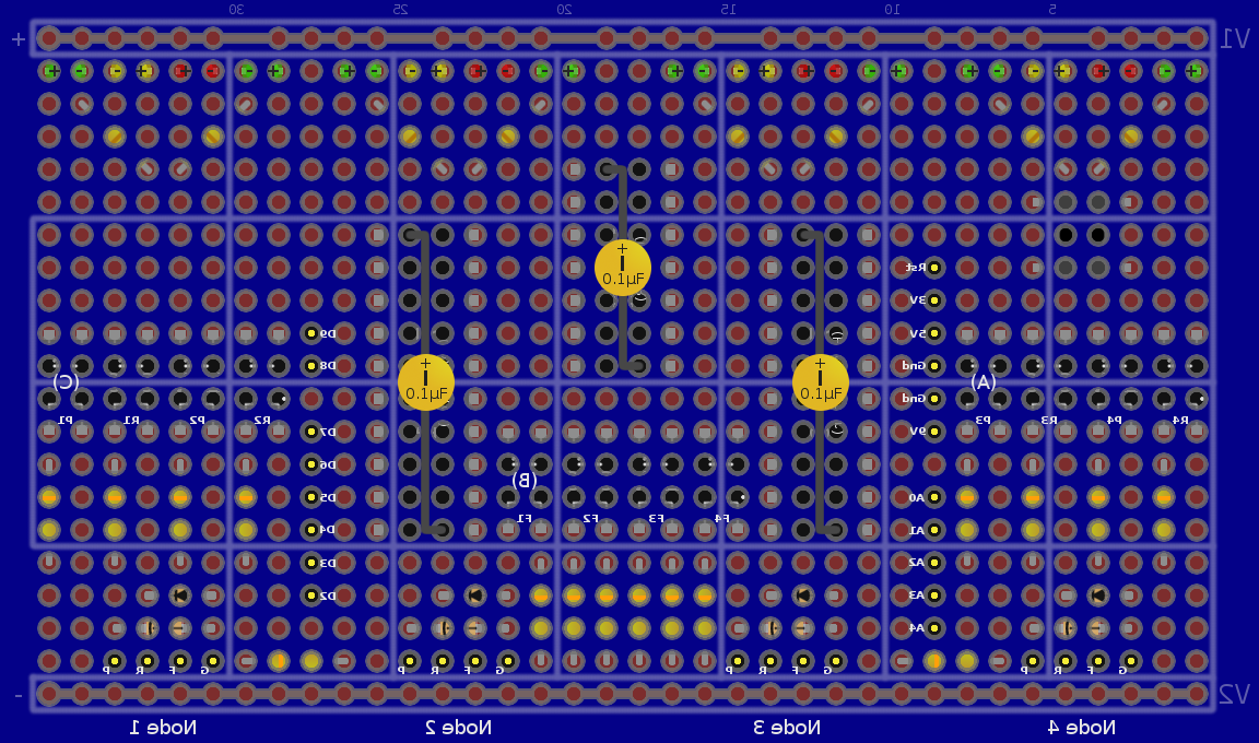
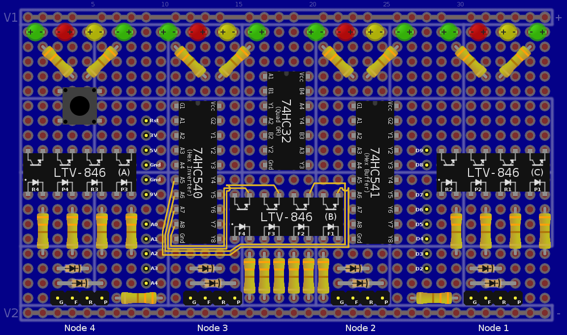
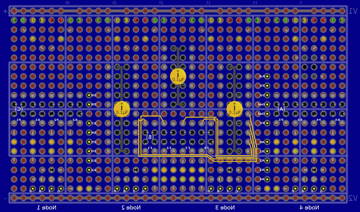
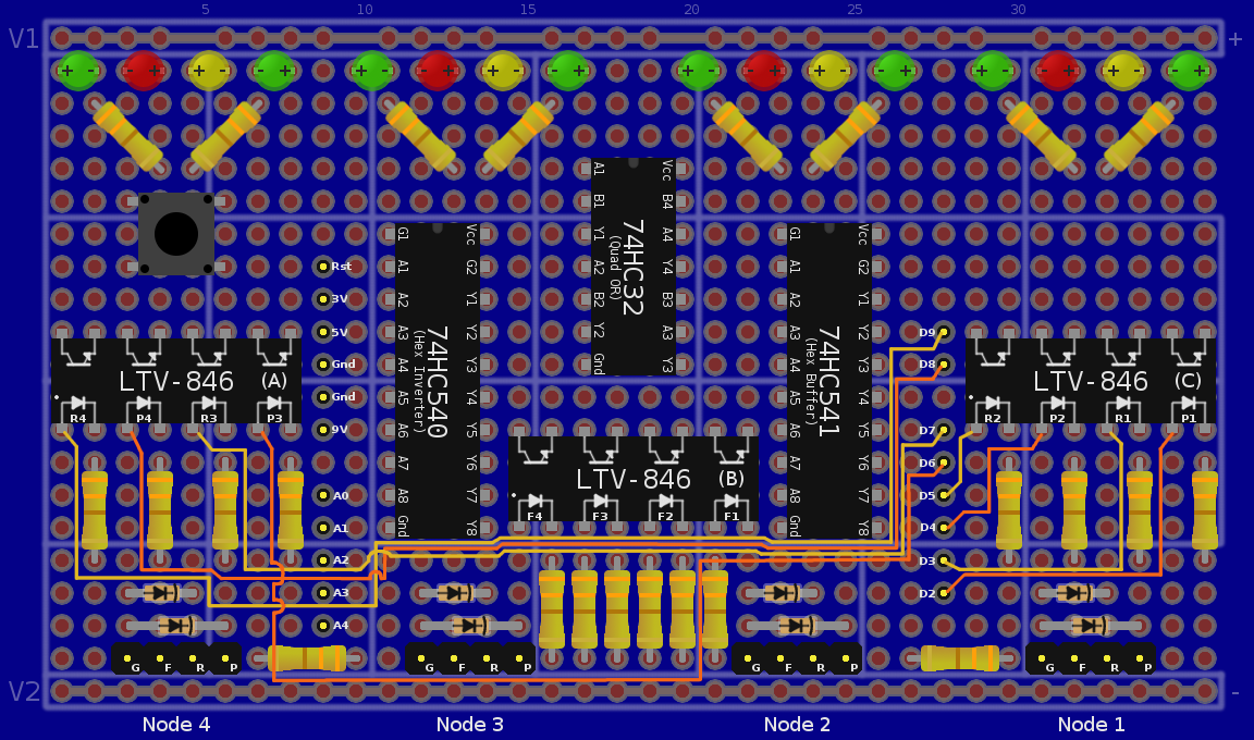
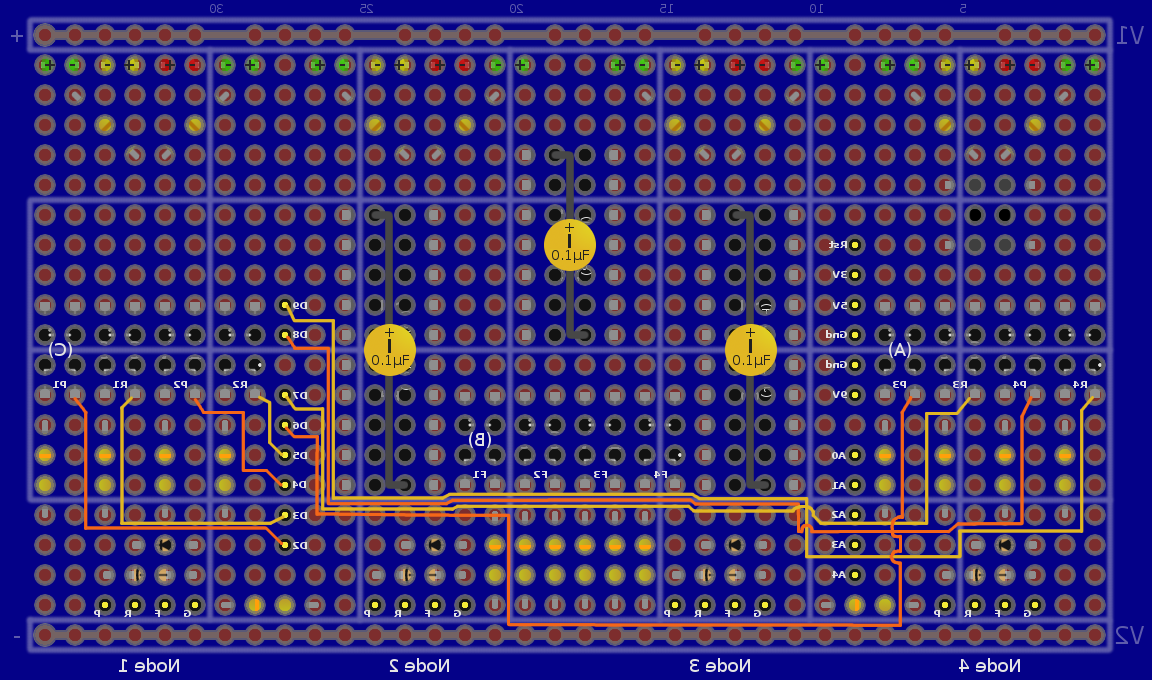
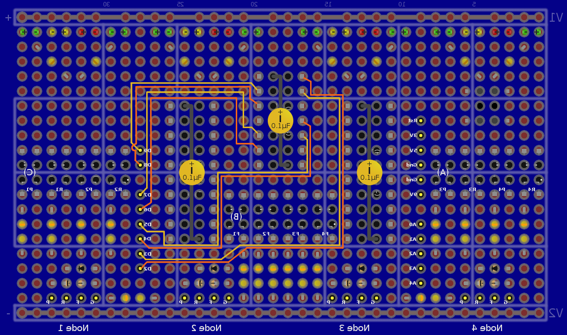
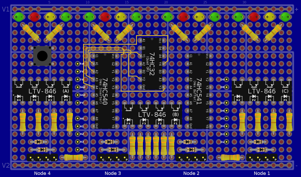
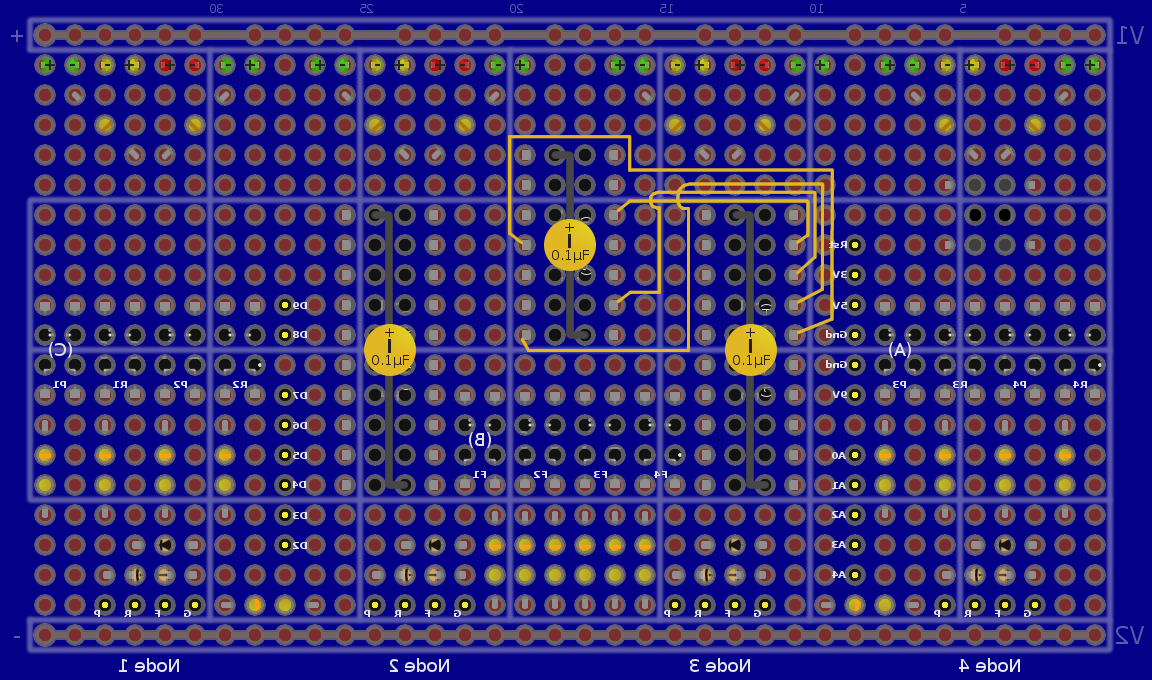
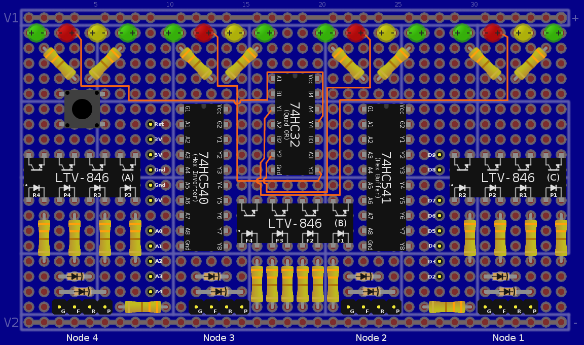
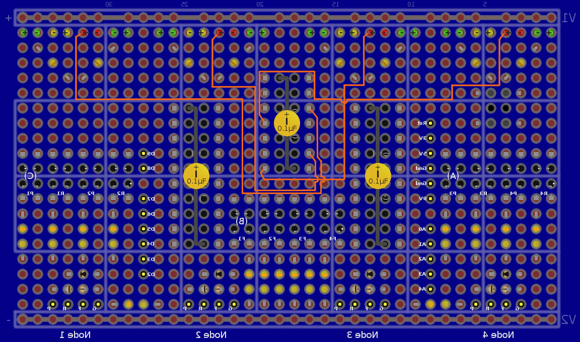
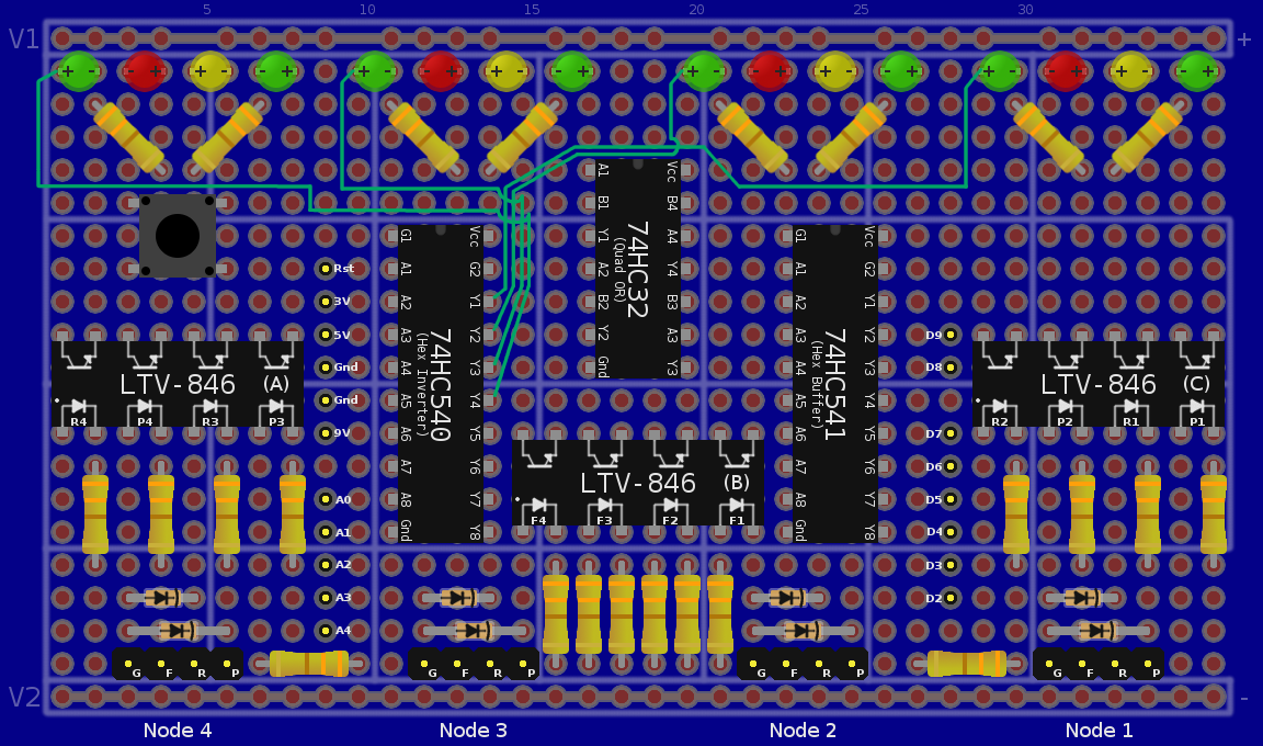
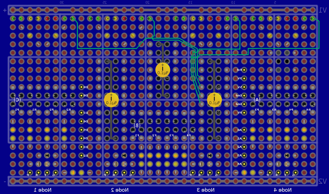
Individual Build Images
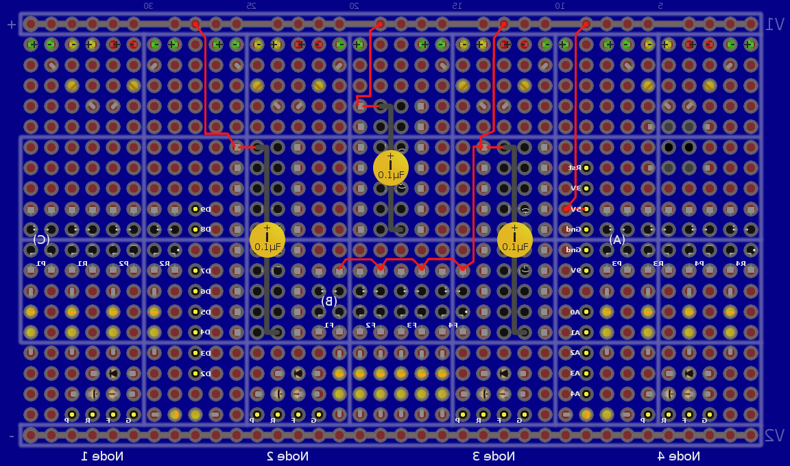
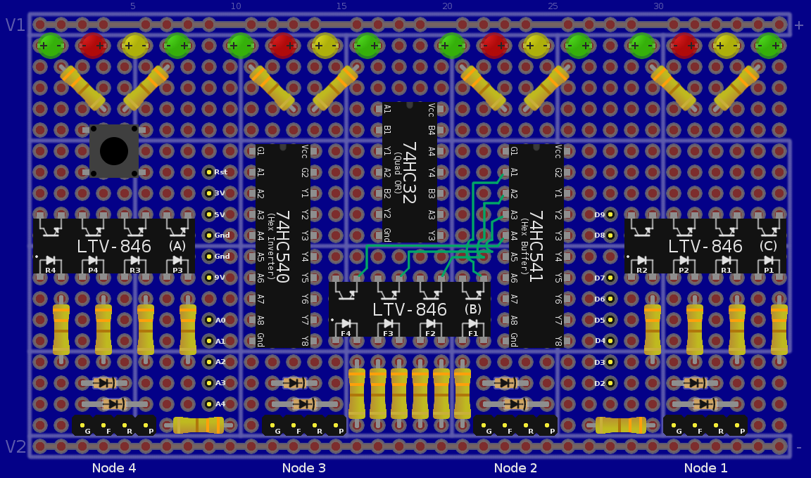
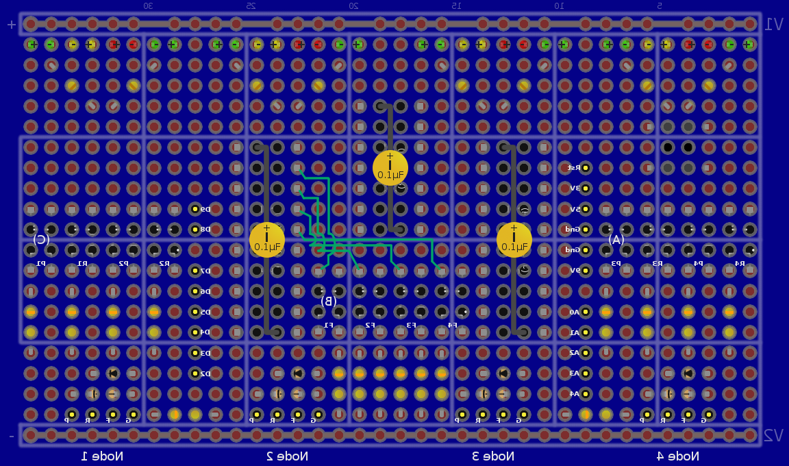
The following table is best viewed on a wide screen display at high resolution.
| Input, advice, complaints and meanderings all welcome! | ||||
| Digimer | digimer@alteeve.ca | https://alteeve.ca/w | legal stuff: | |
| All info is provided "As-Is". Do not use anything here unless you are willing and able to take resposibility for your own actions. © 1997-2013 | ||||
| Naming credits go to Christopher Olah! | ||||
| In memory of Kettle, Tonia, Josh, Leah and Harvey. In special memory of Hannah, Jack and Riley. | ||||
