Node Assassin - Original: Difference between revisions
No edit summary |
|||
| Line 112: | Line 112: | ||
It uses the [[LTV-846]] opto-isolators to isolate the node's power supplies. I use, though it's optional, [[SN74LS04]] inverters to toggle between two status LEDs per port. | It uses the [[LTV-846]] opto-isolators to isolate the node's power supplies. I use, though it's optional, [[SN74LS04]] inverters to toggle between two status LEDs per port. | ||
== v1.1.2 Notes == | |||
* Look for <span class="code">0805</span> or <span class="code">1206</span> resistors to save space. | * Look for <span class="code">0805</span> or <span class="code">1206</span> resistors to save space. | ||
* Switch out the 2x [[SN74LS04]] for 1x [[74ABT540]]. | * Switch out the 2x [[SN74LS04]] for 1x [[74ABT540]]. | ||
Revision as of 16:58, 15 February 2010
|
Node Assassin :: Node Assassin - Original |
-=] Paradise by the node assassin light [=-

Node Assassin is an open-source, open-hardware project to create a network-attached cluster fence device.
Of course, you must proceed at your own risk. :)
First Version
The first version of Node Assassin is operational!
It still needs to be tied into Red Hat's 'ricci' and 'luci' programs to function as a fence device though. This fence device resides on the cluster's private network channel (or some other common intranet).
Software
This is the initial release of the fence control software; Node Assassin Operating System.
Source Code and notes:
Version Control
All software related to this product is hosted on GitHub.
Naos v1.x Protocol
It works by listening for a connection on TCP port 238 on IP 192.168.1.66 (both port and IP are configurable). Once connected, it uses a very simple protocol.
Commands are:
Get the state of all nodes:
00:0
This will generate a message like:
Node states:
- Max Node: 05
- Node 01: Running
- Node 02: Running
- Node 03: Running
- Node 04: Running
- Node 05: Running
End Message.
Any node that is currently fenced will read 'Fenced!'.
Fence node '02' (Supports nodes from 01 to 05):
02:0
This will generate a message like:
Node 02:0: Now Fenced!
Release '02':
02:1
This will generate a message like:
Node 02:1: Now running.
Fencing or releasing other nodes is a simple as replacing '02' above with the node number. The design allows for the expansion of ports up to 99 devices. It should be trivial to go beyond that, but it's a sufficiently high number for now.
Once a node is fenced, the caller can release and the state will be held until either another call releases the fence or the Node Assassin is reset.
Fence Agent
This is (will be...) the cman fence agent for Node Assassin.
#!/usr/bin/perl
#
# Node Assassin - Fence Agent
# Digimer; digimer@alteeve.com
# Feb. 12, 2010.
# Version: 0.1.001
#
# Bugs;
# - None known.
#

# Play safe!
use strict;
use warnings;
use IO::Handle;

# Log file for output.
my $log_file="/tmp/fence_na.log";
my $log=IO::Handle->new();
open ($log, ">$log_file") || die "Failed to open: [$log_file] for writing; Error: $!\n";

# Let's see what we were asked to do.
print $log "Got args:\n";
print "Got args:\n";
foreach my $arg (@ARGV)
{
	print $log "- $arg\n";
	print "- $arg\n";
}
print $log "Done.\n";
print "Done.\n";
$log->close();

exit(0);
Hardware
This is v1.1 of the Node Assassin hardware.
Feb. 08, 2010: New version design has been updated to use discreet status LEDs instead of the bi-colour LEDs because there was some leakage causing the isolators to momentarily trip when the controller (re)booted.
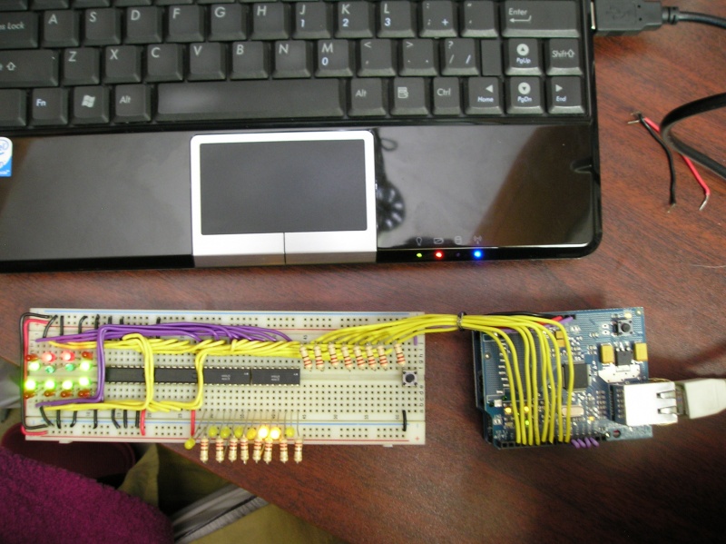
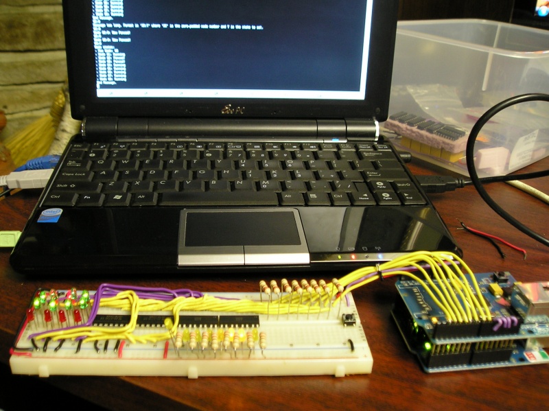
This device is based on the Arduino Duemilanove using the Ethernet Shield for communication.
It uses the LTV-846 opto-isolators to isolate the node's power supplies. I use, though it's optional, SN74LS04 inverters to toggle between two status LEDs per port.
v1.1.2 Notes
- Look for 0805 or 1206 resistors to save space.
- Switch out the 2x SN74LS04 for 1x 74ABT540.
- Swap out the 220ohm resistors for 330ohm and add resistors to the inverter-fed status LEDs.
- Add diodes to the isolated side of the circuits to protect against incorrectly connected reset switches.
- Use 511-1334-ND bi-color LEDs with Mark's updated circuit design.
Old Designs
Pictures
This will be updated as the build comes along. Once I am done I will post a diagram. No sense sharing my bugs at this point.


| Input, advice, complaints and meanderings all welcome! | ||||
| Digimer | digimer@alteeve.ca | https://alteeve.ca/w | legal stuff: | |
| All info is provided "As-Is". Do not use anything here unless you are willing and able to take resposibility for your own actions. © 1997-2013 | ||||
| Naming credits go to Christopher Olah! | ||||
| In memory of Kettle, Tonia, Josh, Leah and Harvey. In special memory of Hannah, Jack and Riley. | ||||