Node Assassin - Original: Difference between revisions
| Line 11: | Line 11: | ||
= Current Status = | = Current Status = | ||
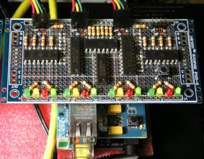
'''Mar. 29, 2010''': The full-sized version of [[NA v1.1.4|v1.1.4]] is coming along nicely. I've added pull-down resistors after a fellow hacklab'er caught them missing from the input side. I'll need to update the block diagram too, as I also moved the feed resistors to not resist the line going to the inputs. I should get that done tomorrow. | |||
'''Mar. 26, 2010''': Some work stress has been slowing down [[NA v1.1.4 Protoshield Variant|v1.1.4]], but it is progressing (see link for updates). I've come to one conclusion though; You must be quite patient and steady handed to make this circuit on the protoshield. As soon as it's done, and possibly sooner depending on how many bugs I find in this board, I will be making a full-size version. I suspect building it on a proper sized protoboard will be *much* faster. | '''Mar. 26, 2010''': Some work stress has been slowing down [[NA v1.1.4 Protoshield Variant|v1.1.4]], but it is progressing (see link for updates). I've come to one conclusion though; You must be quite patient and steady handed to make this circuit on the protoshield. As soon as it's done, and possibly sooner depending on how many bugs I find in this board, I will be making a full-size version. I suspect building it on a proper sized protoboard will be *much* faster. | ||
Revision as of 05:31, 29 March 2010
|
Node Assassin :: Node Assassin - Original |
-=] Paradise by the node assassin light [=-
Node Assassin is an open-source, open-hardware project to create a network-attached cluster fence device.
Of course, you must proceed at your own risk. :)

Current Status
Mar. 29, 2010: The full-sized version of v1.1.4 is coming along nicely. I've added pull-down resistors after a fellow hacklab'er caught them missing from the input side. I'll need to update the block diagram too, as I also moved the feed resistors to not resist the line going to the inputs. I should get that done tomorrow.
Mar. 26, 2010: Some work stress has been slowing down v1.1.4, but it is progressing (see link for updates). I've come to one conclusion though; You must be quite patient and steady handed to make this circuit on the protoshield. As soon as it's done, and possibly sooner depending on how many bugs I find in this board, I will be making a full-size version. I suspect building it on a proper sized protoboard will be *much* faster.
Mar. 19, 2010: Finished the circuit diagram for NA v1.1.4 and the circuit diagram and board layout for the Arduino variant. Once built I will be able to finish the next iteration of NAOS.
Mar. 14, 2010: Added support for Node Assassin to the cluster.conf XML validation file cluster.ng.
Mar. 10, 2010: Progress will be slow here while I divert back to working on the 2-Node CentOS5 Cluster paper that this device was built for. Updates will resume here once the next version of the hardware is built. That is, the new version with independent power feed sensing to determine more reliably the state of a node.
Mar. 08, 2010: Updated the fence agent to v0.1.005.
Mar. 07, 2010: HUGE SUCCESS! For the first time ever, I was able to use the fence_tool to successfully fence a node using Node Assassin! Granted, I had to lie about checking the node's state directly, but hey, the fence agent works!
Mar. 06, 2010: Now working on adding a sense port for each node and to increase the number of I/O ports to a sufficiently high number to support 8 nodes (w/ 2 in + 1 out each).
Mar. 05, 2010: The Fence Agent should now fully support calls from fenced! It hasn't been tested yet, that is the next step. However, it does follow the Fence Agent API.
Mar. 01, 2010: The Fence Agent is now able to fully control Node Assassin. Next step is to set it up from control by CMAN.
Feb. 28, 2010: Release NAOS ver. 1.0.3. Now working on the fence agent.
Feb. 27, 2010: With the na_v1.1.3 prototype complete, I will now be turning my attention to this fence agent. Progress should be noticeable from here on in.
First Version
The first version of Node Assassin is operational! Also, the initial version of the 'fence_na' fencing agent and associated files are done.
This fence device resides on the cluster's private network channel (or some other common intranet).
Software
This is the initial release of the fence control software; Node Assassin Operating System.
Source Code and notes:
Version Control
Note: The code there is seriously out of date. I'll update it later. For now, grab code from this website directly.
All software related to this product is hosted on GitHub.
Naos v1.x Protocol
It works by listening for a connection on TCP port 238 on IP 192.168.1.66 (both port and IP are configurable). Once connected, it uses a very simple protocol.
Queries
Any message starting with 00:x are query commands. That is, the integer represented by x represents a type of query for the node assassin.
Get the state of all nodes:
00:0
This will generate a message like:
Node states:
- Max Node: 08
- Node 01: Running
- Node 02: Running
- Node 03: Running
- Node 04: Running
- Node 05: Running
- Node 06: Running
- Node 07: Running
- Node 08: Running
End Message.
Get information on the node assassin device:
00:1
This will generate a message like:
Node info:
- Node Name: ..... Ariel
- NAOS Version: .. v1.0.3
- Serial Number: . NA0001
- Build Date: .... 2010-02-26
- MAC address: ... 00:09:30:ff:f0:8a
- IP address: .... 192.168.1.66
- Subnet Mask: ... 255.255.255.0
- Default Gateway: 192.168.1.1
End Message.
Any node that is currently fenced will read 'Fenced!'.
Commands
Any string starting with a non-zero integer, like 02:x, will be interpreted as a command meant to be executed on a node. An integer represented by the x will be the command to execute.
Valid commands are:
- xx:0 - Fence the node and keep it fenced.
- xx:1 - Release the fence and allow the node to boot.
- xx:2 - (Re)boot a node. This will close the switch for 1 second. This is useful when connecting a port to a node's power switch to send a graceful power-off via ACPI or to boot a powered-down server.
- xx:3 - Force a power-off on a node. This will close the switch for 10 seconds, forcing a locked up node to power down. This is useless when connected to a reset switch and is meant to be used when a port is connected to a power switch.
Examples:
Fence node '02' (Supports nodes from 01 to 08):
02:0
This will generate a message like:
Node 02:0: Now Fenced!
Release '02':
02:1
This will generate a message like:
Node 02:1: Fence released!
Fencing or releasing other nodes is a simple as replacing '02' above with the node number. The design allows for the expansion of ports up to 99 devices. It should be trivial to go beyond that, but it's a sufficiently high number for now.
Once a node is fenced, the caller can release and the state will be held until either another call releases the fence or the Node Assassin is reset.
Fence Agent
This is the CMAN fence agent for Node Assassin.
The Node Assassin fence agent v0.1.005 is broken up into three files:
- Source: fence_na - Download
- This is the core fence agent that exists in /sbin/.
- Source: fence_na.lib - Download
- This is the fence agent's function library that exists in /etc/na/.
- Source: fence_na.conf - Download
- This is the common Node Assassin configuration file that exists in /etc/na/.
The reason for the three files is that, later, there will be a fourth executable that will program the Node Assassin devices. When this program is created, it will consult the common configuration file and will use some of the functions in the library.
To test the agent, copy the following into a file (ie: args.txt):
# Test file used as input for the NA fence agent.
ipaddr=ariel.alteeve.com
port=1
login=ariel
passwd=gr0tt0
action=on
And cat it into the fence agent via a pipe:
clear; cat args.txt | ./fence_na
XML Validation Support
Until Node Assassin is natively supported, you will need to update the cluster.ng validation file for cluster.conf to successfully validate.
To accomplish this, you will need to modify or replace the default /usr/share/system-config-cluster/misc/cluster.ng to match this one:
The diff between the default version and the version above should be:
diff /usr/share/system-config-cluster/misc/cluster.ng /root/backups/cluster.ng
47,62d46
<        <!-- Node Assassin -->
<        <group>
<         <attribute name="ipaddr"/>
<         <optional>
<         <attribute name="login"/>
<         </optional>
<         <optional>
<         <attribute name="passwd"/>
<         </optional>
<         <optional>
<         <attribute name="passwd_script"/>
<         </optional>
<         <optional>
<          <attribute name="quiet"/>
<         </optional>
<        </group>
1062,1066d1045
<         <!-- Node Assassin -->
<         <group>
<          <attribute name="port"/>
<          <attribute name="action"/>
<         </group>
Hardware
v1.1.4
Mar. 6, 2010: Started work on:
- na v1.1.4 - Full bank of bicolour status LEDS, won't fit on the protoshield.
- na v1.1.4 Minimal - Two single-colour LED status, will fit on the protoshield.
This version will add read pins connected to each node's power LED to check a node's power state independent of the node port state. This is required to meet the FenceAgentAPI requirements.
Feb. 20, 2010: Current version:
NOTE: No longer true... see v.1.1.4. In short; Need independent verification of node death. This is the final revision of the Node Assassin hardware for the first release of the hardware.
v1.1.3
Availability of parts forced a slight change from v1.1.2 to this version:
- Based on the Arduino Duemilanove using the Ethernet Shield for communication.
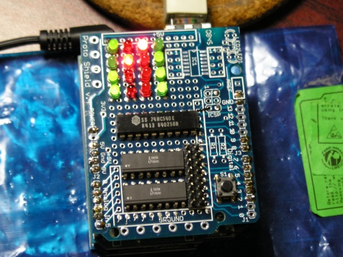
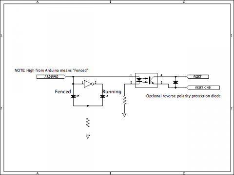
- Arduino's digital pins #2-9 set to output through 330Ω resistors to 2x LTV-846 opto-isolators which opens and closes a given node's reset switch. Supports up to 8 nodes at the moment.
- 74HC540E 8-Input Inverter for the status LEDs.
- 1N4148 diodes prevent improper connection of the reset connectors by providing a closed circuit when the reset switch's +5vcc is connected to the ground pin.
- 8x green and 8x red low-power LEDs are are paired up per circuit to show the status of each port.
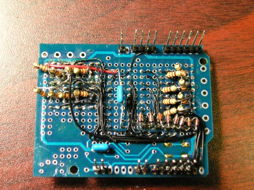
- 16x 330Ω resistors. Each Open/Fenced status LED pair's grounds are tied together and connected to ground via a resistor and the Arduino pins going through the optoisolators are tied to ground through a resistor.
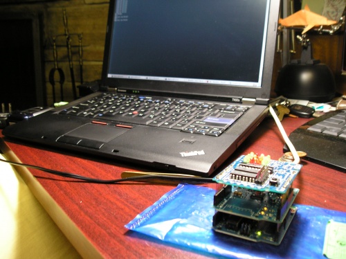
- An Arduino Proto Shield v.4 is used to assemble the components onto an Arduino-compatible shield. Given the size restrictions, wire-wrap wire is used to provide connections. It's messy, but it works.
Feb. 27, 2010: The initial proto-board is done!
I still need to do up proper schematics. I will do that shortly.
Per circuit design:
Case
Old Versions
| Input, advice, complaints and meanderings all welcome! | ||||
| Digimer | digimer@alteeve.ca | https://alteeve.ca/w | legal stuff: | |
| All info is provided "As-Is". Do not use anything here unless you are willing and able to take resposibility for your own actions. © 1997-2013 | ||||
| Naming credits go to Christopher Olah! | ||||
| In memory of Kettle, Tonia, Josh, Leah and Harvey. In special memory of Hannah, Jack and Riley. | ||||