2-Node Red Hat KVM Cluster Tutorial - Archive
|
AN!Wiki :: How To :: 2-Node Red Hat KVM Cluster Tutorial - Archive |
| Warning: Until this is removed, this tutorial is incomplete and should be used cautiously. If you wish to follow it and run into problems or have questions, please drop me a line. |
| Note: This is the second edition of the original Red Hat Cluster Service 2 Tutorial. This version is updated to use the Red Hat Cluster Suite, Stable version 3. It replaces Xen in favour of KVM to stay in-line with Red Hat's supported configuration. It also uses corosync, replacing openais, as the core cluster communication stack. |
This paper has one goal;
- Creating a 2-node, high-availability cluster hosting KVM virtual machines using RHCS "stable 3" with DRBD and clustered LVM for synchronizing storage data. This is an updated version of the earlier Red Hat Cluster Service 2 Tutorial Tutorial. You will find much in common with that tutorial if you've previously followed that document. Please don't skip large sections though. There are some differences that are subtle but important.
Grab a coffee, put on some nice music and settle in for some geekly fun.
The Task Ahead
Before we start, let's take a few minutes to discuss clustering and it's complexities.
Technologies We Will Use
- Red Hat Enterprise Linux 6 (EL6); You can use a derivative like CentOS v6.
- Red Hat Cluster Services "Stable" version 3. This describes the following core components:
- Corosync; Provides cluster communications using the totem protocol.
- Cluster Manager (cman); Manages the starting, stopping and managing of the cluster.
- Resource Manager (rgmanager); Manages cluster resources and services. Handles service recovery during failures.
- Clustered Logical Volume Manager (clvm); Cluster-aware (disk) volume manager. Backs GFS2 filesystems and KVM virtual machines.
- Global File Systems version 2 (gfs2); Cluster-aware, concurrently mountable file system.
- Distributed Redundant Block Device (DRBD); Keeps shared data synchronized across cluster nodes.
- KVM; Hypervisor that controls and supports virtual machines.
A Note on Hardware
In this tutorial, I will make reference to specific hardware components and devices. I do this to share what devices and equipment I use, but I do not endorse any of the products named in this tutorial. I am in no way affiliated with any hardware vendor not do I receive any compensation or gifts from any company.
A Note on Patience
When someone wants to become a pilot, they can't jump in a plane and try to take off. It's not that flying is inherently hard, but it requires a foundation of understanding. Clustering is the same is this regard; There are many different pieces that have to work together to just get off the ground.
You must have patience.
Like a pilot of their first flight, seeing a cluster come to life is a fantastic experience. Don't rush it! Do your homework and you'll be on your way before you know it.
Coming back to earth;
Many technologies can be learned by creating a very simple base and then building on it. The classic "Hello, World!" script created when first learning a programming language is an example of this. Unfortunately, there is no real analogue to this in clustering. Even the most basic cluster requires several pieces be in place and working together. If you try to rush by ignoring pieces you think are not important, you will almost certainly waste time. A good example is setting aside fencing, thinking that your test cluster's data isn't important. The cluster software has no concept of "test". It treats everything as critical all the time and will shut down if anything goes wrong.
Take your time, work through these steps, and you will have the foundation cluster sooner than you realize. Clustering is fun because it is a challenge.
Prerequisites
It is assumed that you are familiar with Linux systems administration, specifically Red Hat Enterprise Linux and its derivatives. You will need to have somewhat advanced networking experience as well. You should be comfortable working in a terminal (directly or over ssh). Familiarity with XML will help, but is not terribly required as it's use here is pretty self-evident.
If you feel a little out of depth at times, don't hesitate to set this tutorial aside. Branch over to the components you feel the need to study more, then return and continue on. Finally, and perhaps most importantly, you must have patience! If you have a manager asking you to "go live" with a cluster in a month, tell him or her that it simply won't happen. If you rush, you will skip important points and you will fail.
Patience is vastly more important than any pre-existing skill.
Focus and Goal
There is a different cluster for every problem. Generally speaking though, there are two main problems that clusters try to resolve; Performance and High Availability. Performance clusters are generally tailored to the application requiring the performance increase. There are some general tools for performance clustering, like Red Hat's LVS (Linux Virtual Server) for load-balancing common applications like the Apache web-server.
This tutorial will focus on High Availability clustering, often shortened to simply HA and not to be confused with the Linux-HA "heartbeat" cluster suite, which we will not be using here. The cluster will provide a shared file systems and will provide for the high availability on KVM-based virtual servers. The goal will be to have the virtual servers live-migrate during planned node outages and automatically restart on a surviving node when the original host node fails.
Below is a very brief overview;
High Availability clusters like ours have two main parts; Cluster management and resource management.
The cluster itself is responsible for maintaining the cluster nodes in a group. This group is part of a "Closed Process Group", or CPG. When a node fails, the cluster manager must detect the failure, reliably eject the node from the cluster using fencing and then reform the CPG. Each time the cluster changes, or "re-forms", the resource manager is called. The resource manager checks to see how the cluster changed, consults it's configuration and determines what to do, if anything.
The details of all this will be discussed in detail a little later on. For now, it's sufficient to have in mind these two major roles and understand that they are somewhat independent entities.
Platform
This tutorial was written using RHEL version 6.2, x86_64 architecture. No attempt was made to test on i686 or other EL6 derivatives. That said, there is no reason to believe that this tutorial will not apply to any variant. As much as possible, the language will be distro-agnostic. It is advised that you use an x86_64 (64-bit) platform if at all possible.
A Word On Complexity
Introducing the Fabimer Principle:
Clustering is not inherently hard, but it is inherently complex. Consider;
- Any given program has N bugs.
- RHCS uses; cman, corosync, dlm, fenced, rgmanager, and many more smaller apps.
- We will be adding DRBD, GFS2, clvmd, libvirtd and KVM.
- Right there, we have N^10 possible bugs. We'll call this A.
- A cluster has Y nodes.
- In our case, 2 nodes, each with 3 networks across 6 interfaces bonded into pairs.
- The network infrastructure (Switches, routers, etc). We will be using two managed switches, adding another layer of complexity.
- This gives us another Y^(2*(3*2))+2, the +2 for managed switches. We'll call this B.
- Let's add the human factor. Let's say that a person needs roughly 5 years of cluster experience to be considered an proficient. For each year less than this, add a Z "oops" factor, (5-Z)^2. We'll call this C.
- So, finally, add up the complexity, using this tutorial's layout, 0-years of experience and managed switches.
- (N^10) * (Y^(2*(3*2))+2) * ((5-0)^2) == (A * B * C) == an-unknown-but-big-number.
This isn't meant to scare you away, but it is meant to be a sobering statement. Obviously, those numbers are somewhat artificial, but the point remains.
Any one piece is easy to understand, thus, clustering is inherently easy. However, given the large number of variables, you must really understand all the pieces and how they work together. DO NOT think that you will have this mastered and working in a month. Certainly don't try to sell clusters as a service without a lot of internal testing.
Clustering is kind of like chess. The rules are pretty straight forward, but the complexity can take some time to master.
Overview of Components
When looking at a cluster, there is a tendency to want to dive right into the configuration file. That is not very useful in clustering.
- When you look at the configuration file, it is quite short.
It isn't like most applications or technologies though. Most of us learn by taking something, like a configuration file, and tweaking it this way and that to see what happens. I tried that with clustering and learned only what it was like to bang my head against the wall.
- Understanding the parts and how they work together is critical.
You will find that the discussion on the components of clustering, and how those components and concepts interact, will be much longer than the initial configuration. It is true that we could talk very briefly about the actual syntax, but it would be a disservice. Please, don't rush through the next section or, worse, skip it and go right to the configuration. You will waste far more time than you will save.
- Clustering is easy, but it has a complex web of inter-connectivity. You must grasp this network if you want to be an effective cluster administrator!
Component; cman
This was, traditionally, the cluster manager. In the 3.0 series, which is what all versions of EL6 will use, cman acts mainly as a quorum provider, tallying votes and deciding on a critical property of the cluster: quorum. As of the 3.1 series, which future EL releases will use, cman will be removed entirely.
The cman service is used to start and stop the cluster communication, membership, locking, fencing and other cluster foundation applications.
Component; corosync
Corosync is the heart of the cluster. Almost all other cluster compnents operate though this.
In Red Hat clusters, corosync is configured via the central cluster.conf file. It can be configured directly in corosync.conf, but given that we will be building an RHCS cluster, we will only use cluster.conf. That said, almost all corosync.conf options are available in cluster.conf. This is important to note as you will see references to both configuration files when searching the Internet.
Corosync sends messages using multicast messaging by default. Recently, unicast support has been added, but due to network latency, it is only recommended for use with small clusters of two to four nodes. We will be using multicast in this tutorial.
A Little History
There were significant changes between RHCS version 2, which we are using, and version 3 available on EL6 and recent Fedoras.
In the RHCS version 2, there was a component called openais which provided totem. The OpenAIS project was designed to be the heart of the cluster and was based around the Service Availability Forum's Application Interface Specification. AIS is an open API designed to provide inter-operable high availability services.
In 2008, it was decided that the AIS specification was overkill for most clustered applications being developed in the open source community. At that point, OpenAIS was split in to two projects: Corosync and OpenAIS. The former, Corosync, provides totem, cluster membership, messaging, and basic APIs for use by clustered applications, while the OpenAIS project became an optional add-on to corosync for users who want the full AIS API.
You will see a lot of references to OpenAIS while searching the web for information on clustering. Understanding it's evolution will hopefully help you avoid confusion.
Concept; quorum
Quorum is defined as the minimum set of hosts required in order to provide clustered services and is used to prevent split-brain situations.
The quorum algorithm used by the RHCS cluster is called "simple majority quorum", which means that more than half of the hosts must be online and communicating in order to provide service. While simple majority quorum a very common quorum algorithm, other quorum algorithms exist (grid quorum, YKD Dyanamic Linear Voting, etc.).
The idea behind quorum is that, when a cluster splits into two or more partitions, which ever group of machines has quorum can safely start clustered services knowing that no other lost nodes will try to do the same.
Take this scenario;
- You have a cluster of four nodes, each with one vote.
- The cluster's expected_votes is 4. A clear majority, in this case, is 3 because (4/2)+1, rounded down, is 3.
- Now imagine that there is a failure in the network equipment and one of the nodes disconnects from the rest of the cluster.
- You now have two partitions; One partition contains three machines and the other partition has one.
- The three machines will have quorum, and the other machine will lose quorum.
- The partition with quorum will reconfigure and continue to provide cluster services.
- The partition without quorum will withdraw from the cluster and shut down all cluster services.
When the cluster reconfigures and the partition wins quorum, it will fence the node(s) in the partition without quorum. Once the fencing has been confirmed successful, the partition with quorum will begin accessing clustered resources, like shared filesystems.
This also helps explain why an even 50% is not enough to have quorum, a common question for people new to clustering. Using the above scenario, imagine if the split were 2 and 2 nodes. Because either can't be sure what the other would do, neither can safely proceed. If we allowed an even 50% to have quorum, both partition might try to take over the clustered services and disaster would soon follow.
There is one, and only one except to this rule.
In the case of a two node cluster, as we will be building here, any failure results in a 50/50 split. If we enforced quorum in a two-node cluster, there would never be high availability because and failure would cause both nodes to withdraw. The risk with this exception is that we now place the entire safety of the cluster on fencing, a concept we will cover in a second. Fencing is a second line of defense and something we are loath to rely on alone.
Even in a two-node cluster though, proper quorum can be maintained by using a quorum disk, called a qdisk. Unfortunately, qdisk on a DRBD resource comes with it's own problems, so we will not be able to use it here.
Concept; Virtual Synchrony
Many cluster operations, like distributed locking and so on, have to occur in the same order across all nodes. This concept is called "virtual synchrony".
This is provided by corosync using "closed process groups", CPG. A closed process group is simply a private group of processes in a cluster. Within this closed group, all messages between members are ordered. Delivery, however, is not guaranteed. If a member misses messages, it is up to the member's application to decide what action to take.
Let's look at two scenarios showing how locks are handled using CPG;
- The cluster starts up cleanly with two members.
- Both members are able to start service:foo.
- Both want to start it, but need a lock from DLM to do so.
- The an-node01 member has it's totem token, and sends it's request for the lock.
- DLM issues a lock for that service to an-node01.
- The an-node02 member requests a lock for the same service.
- DLM rejects the lock request.
- The an-node01 member successfully starts service:foo and announces this to the CPG members.
- The an-node02 sees that service:foo is now running on an-node01 and no longer tries to start the service.
- The two members want to write to a common area of the /shared GFS2 partition.
- The an-node02 sends a request for a DLM lock against the FS, gets it.
- The an-node01 sends a request for the same lock, but DLM sees that a lock is pending and rejects the request.
- The an-node02 member finishes altering the file system, announces the changed over CPG and releases the lock.
- The an-node01 member updates it's view of the filesystem, requests a lock, receives it and proceeds to update the filesystems.
- It completes the changes, annouces the changes over CPG and releases the lock.
Messages can only be sent to the members of the CPG while the node has a totem tokem from corosync.
Concept; Fencing
| Warning: DO NOT BUILD A CLUSTER WITHOUT PROPER, WORKING AND TESTED FENCING. |
Fencing is a absolutely critical part of clustering. Without fully working fence devices, your cluster will fail.
Sorry, I promise that this will be the only time that I speak so strongly. Fencing really is critical, and explaining the need for fencing is nearly a weekly event.
So then, let's discuss fencing.
When a node stops responding, an internal timeout and counter start ticking away. During this time, no DLM locks are allowed to be issued. Anything using DLM, including rgmanager, clvmd and gfs2, are effectively hung. The hung node is detected using a totem token timeout. That is, if a token is not received from a node within a period of time, it is considered lost and a new token is sent. After a certain number of lost tokens, the cluster declares the node dead. The remaining nodes reconfigure into a new cluster and, if they have quorum (or if quorum is ignored), a fence call against the silent node is made.
The fence daemon will look at the cluster configuration and get the fence devices configured for the dead node. Then, one at a time and in the order that they appear in the configuration, the fence daemon will call those fence devices, via their fence agents, passing to the fence agent any configured arguments like username, password, port number and so on. If the first fence agent returns a failure, the next fence agent will be called. If the second fails, the third will be called, then the forth and so on. Once the last (or perhaps only) fence device fails, the fence daemon will retry again, starting back at the start of the list. It will do this indefinitely until one of the fence devices success.
Here's the flow, in point form:
- The totem token moves around the cluster members. As each member gets the token, it sends sequenced messages to the CPG members.
- The token is passed from one node to the next, in order and continuously during normal operation.
- Suddenly, one node stops responding.
- A timeout starts (~238ms by default), and each time the timeout is hit, and error counter increments and a replacement token is created.
- The silent node responds before the failure counter reaches the limit.
- The failure counter is reset to 0
- The cluster operates normally again.
- Again, one node stops responding.
- Again, the timeout begins. As each totem token times out, a new packet is sent and the error count increments.
- The error counts exceed the limit (4 errors is the default); Roughly one second has passed (238ms * 4 plus some overhead).
- The node is declared dead.
- The cluster checks which members it still has, and if that provides enough votes for quorum.
- If there are too few votes for quorum, the cluster software freezes and the node(s) withdraw from the cluster.
- If there are enough votes for quorum, the silent node is declared dead.
- corosync calls fenced, telling it to fence the node.
- The fenced daemon notifies DLM and locks are blocked.
- Which fence device(s) to use, that is, what fence_agent to call and what arguments to pass, is gathered.
- For each configured fence device:
- The agent is called and fenced waits for the fence_agent to exit.
- The fence_agent's exit code is examined. If it's a success, recovery starts. If it failed, the next configured fence agent is called.
- If all (or the only) configured fence fails, fenced will start over.
- fenced will wait and loop forever until a fence agent succeeds. During this time, the cluster is effectively hung.
- Once a fence_agent succeeds, fenced notifies DLM and lost locks are recovered.
- GFS2 partitions recover using their journal.
- Lost cluster resources are recovered as per rgmanager's configuration (including file system recovery as needed).
- Normal cluster operation is restored, minus the lost node.
This skipped a few key things, but the general flow of logic should be there.
This is why fencing is so important. Without a properly configured and tested fence device or devices, the cluster will never successfully fence and the cluster will remain hung until a human can intervene.
Component; totem
The totem protocol defines message passing within the cluster and it is used by corosync. A token is passed around all the nodes in the cluster, and nodes can only send messages while they have the token. A node will keep it's messages in memory until it gets the token back with no "not ack" messages. This way, if a node missed a message, it can request it be resent when it gets it's token. If a node isn't up, it will simply miss the messages.
The totem protocol supports something called 'rrp', Redundant Ring Protocol. Through rrp, you can add a second backup ring on a separate network to take over in the event of a failure in the first ring. In RHCS, these rings are known as "ring 0" and "ring 1". The RRP is being re-introduced in RHCS version 3. It's use is experimental and should only be used with plenty of testing.
Component; rgmanager
When the cluster membership changes, corosync tells the rgmanager that it needs to recheck it's services. It will examine what changed and then will start, stop, migrate or recover cluster resources as needed.
Within rgmanager, one or more resources are brought together as a service. This service is then optionally assigned to a failover domain, an subset of nodes that can have preferential ordering.
The rgmanager daemon runs separately from the cluster manager, cman. This means that, to fully start the cluster, we need to start both cman and then rgmanager.
Component; qdisk
| Note: qdisk does not work reliably on a DRBD resource, so we will not be using it in this tutorial. |
A Quorum disk, known as a qdisk is small partition on SAN storage used to enhance quorum. It generally carries enough votes to allow even a single node to take quorum during a cluster partition. It does this by using configured heuristics, that is custom tests, to decided which which node or partition is best suited for providing clustered services during a cluster reconfiguration. These heuristics can be simple, like testing which partition has access to a given router, or they can be as complex as the administrator wishes using custom scripts.
Though we won't be using it here, it is well worth knowing about when you move to a cluster with SAN storage.
Component; DRBD
DRBD; Distributed Replicating Block Device, is a technology that takes raw storage from two or more nodes and keeps their data synchronized in real time. It is sometimes described as "RAID 1 over Cluster Nodes", and that is conceptually accurate. In this tutorial's cluster, DRBD will be used to provide that back-end storage as a cost-effective alternative to a traditional SAN device.
To help visualize DRBD's use and role, Take a look at how we will implement our cluster's storage.
This shows;
- Each node having four physical disks tied together in a RAID Level 5 array and presented to the Node's OS as a single drive which is found at /dev/sda.
- Each node's OS uses three primary partitions for /boot, <swap> and /.
- Three extended partitions are created;
- All three extended partitions are combined using DRBD to create three DRBD resources;
- /dev/drbd0 is backed by /dev/sda5.
- /dev/drbd1 is backed by /dev/sda6.
- /dev/drbd2 is backed by /dev/sda7.
- All three DRBD resources are managed by clustered LVM.
- The GFS2-formatted LV is mounted on /shared on both nodes.
- Each VM gets it's own LV.
- All three DRBD resources sync over the Storage Network, which uses the bonded bond1 (backed be eth1 and eth4).
Don't worry if this seems illogical at this stage. The main thing to look at are the drbdX devices and how they each tie back to a corresponding sdaY device on either node.
 _________________________________________________                 _________________________________________________
| [ an-node01 ]                                   |               |                                   [ an-node02 ] |
|  ________       __________                      |               |                      __________       ________  |
| [_disk_1_]--+--[_/dev/sda_]                     |               |                     [_/dev/sda_]--+--[_disk_1_] |
|  ________   |    |   ___________    _______     |               |     _______    ___________   |    |   ________  |
| [_disk_2_]--+    +--[_/dev/sda1_]--[_/boot_]    |               |    [_/boot_]--[_/dev/sda1_]--+    +--[_disk_2_] |
|  ________   |    |   ___________    ________    |               |    ________    ___________   |    |   ________  |
| [_disk_3_]--+    +--[_/dev/sda2_]--[_<swap>_]   |               |   [_<swap>_]--[_/dev/sda2_]--+    +--[_disk_3_] |
|  ________   |    |   ___________    ___         |               |         ___    ___________   |    |   ________  |
| [_disk_4_]--/    +--[_/dev/sda3_]--[_/_]        |               |        [_/_]--[_/dev/sda3_]--+    \--[_disk_4_] |
|                  |   ___________                |               |                ___________   |                  |
|                  +--[_/dev/sda5_]------------\  |               |  /------------[_/dev/sda5_]--+                  |
|                  |   ___________             |  |               |  |             ___________   |                  |
|                  +--[_/dev/sda6_]----------\ |  |               |  | /----------[_/dev/sda6_]--+                  |
|                  |   ___________           | |  |               |  | |           ___________   |                  |
|                  \--[_/dev/sda7_]--------\ | |  |               |  | | /--------[_/dev/sda7_]--/                  |
|        _______________    ____________   | | |  |               |  | | |   ____________    _______________        |
|    /--[_Clustered_LVM_]--[_/dev/drbd2_]--/ | |  |               |  | | \--[_/dev/drbd2_]--[_Clustered_LVM_]--\    |
|   _|__                     |   _______     | |  |               |  | |      |   _______                    __|_   |
|  [_PV_]                    \--{_bond1_}    | |  |               |  | |      \--{_bond1_}                  [_PV_]  |
|   _|________                               | |  |               |  | |                               ________|_   |
|  [_an02-vg0_]                              | |  |               |  | |                              [_an02-vg0_]  |
|    |   ________________________    ....... | |  |               |  | |  _____     ________________________   |    |
|    +--[_/dev/an02-vg0/vm0003_1_]---:.vm3.: | |  |               |  | | [_vm3_]---[_/dev/an02-vg0/vm0003_1_]--+    |
|    |   ________________________    ....... | |  |               |  | |  _____     ________________________   |    |
|    \--[_/dev/an02-vg0/vm0004_1_]---:.vm4.: | |  |               |  | | [_vm4_]---[_/dev/an02-vg0/vm0004_1_]--/    |
|          _______________    ____________   | |  |               |  | |   ____________    _______________          |
|      /--[_Clustered_LVM_]--[_/dev/drbd1_]--/ |  |               |  | \--[_/dev/drbd1_]--[_Clustered_LVM_]--\      |
|     _|__                     |   _______     |  |               |  |      |   _______                    __|_     |
|    [_PV_]                    \--{_bond1_}    |  |               |  |      \--{_bond1_}                  [_PV_]    |
|     _|________                               |  |               |  |                               ________|_     |
|    [_an01-vg0_]                              |  |               |  |                              [_an01-vg0_]    |
|      |   ________________________     _____  |  |               |  | .......    ________________________   |      |
|      +--[_/dev/an01-vg0/vm0001_1_]---[_vm1_] |  |               |  | :.vm1.:---[_/dev/an02-vg0/vm0001_1_]--+      |
|      |   ________________________     _____  |  |               |  | .......    ________________________   |      |
|      \--[_/dev/an01-vg0/vm0002_1_]---[_vm2_] |  |               |  | :.vm2.:---[_/dev/an02-vg0/vm0002_1_]--/      |
|            _______________    ____________   |  |               |  |   ____________    _______________            |
|        /--[_Clustered_LVM_]--[_/dev/drbd0_]--/  |               |  \--[_/dev/drbd0_]--[_Clustered_LVM_]--\        |
|       _|__                     |   _______      |               |       |   _______                    __|_       |
|      [_PV_]                    \--{_bond1_}     |               |       \--{_bond1_}                  [_PV_]      |
|       _|__________                              |               |                              __________|_       |
|      [_shared-vg0_]                             |               |                             [_shared-vg0_]      |
|       _|_________________________               |               |               _________________________|_       |
|      [_/dev/shared-vg0/lv_shared_]              |               |              [_/dev/shared-vg0/lv_shared_]      |
|        |   ______    _________                  |               |                  _________    ______   |        |
|        \--[_GFS2_]--[_/shared_]                 |               |                 [_/shared_]--[_GFS2_]--/        |
|                                          _______|   _________   |_______                                          |
|                                         | bond1 =--| Storage |--= bond1 |                                         |
|                                         |______||  | Network |  ||______|                                         |
|_________________________________________________|  |_________|  |_________________________________________________|
.
Component; Clustered LVM
With DRBD providing the raw storage for the cluster, we must next consider partitions. This is where Clustered LVM, known as CLVM, comes into play.
CLVM is ideal in that by using DLM, the distributed lock manager. It won't allow access to cluster members outside of corosync's closed process group, which, in turn, requires quorum.
It is ideal because it can take one or more raw devices, known as "physical volumes", or simple as PVs, and combine their raw space into one or more "volume groups", known as VGs. These volume groups then act just like a typical hard drive and can be "partitioned" into one or more "logical volumes", known as LVs. These LVs are where KVM's virtual machine guests will exist and where we will create our GFS2 clustered file system.
LVM is particularly attractive because of how flexible it is. We can easily add new physical volumes later, and then grow an existing volume group to use the new space. This new space can then be given to existing logical volumes, or entirely new logical volumes can be created. This can all be done while the cluster is online offering an upgrade path with no down time.
Component; GFS2
With DRBD providing the clusters raw storage space, and Clustered LVM providing the logical partitions, we can now look at the clustered file system. This is the role of the Global File System version 2, known simply as GFS2.
It works much like standard filesystem, with user-land tools like mkfs.gfs2, fsck.gfs2 and so on. The major difference is that it and clvmd use the cluster's distributed locking mechanism provided by the dlm_controld daemon. Once formatted, the GFS2-formatted partition can be mounted and used by any node in the cluster's closed process group. All nodes can then safely read from and write to the data on the partition simultaneously.
| Note: GFS2 is only supported when run on top of Clustered LVM LVs. This is because, in certain error states, gfs2_controld will call dmsetup to disconnect the GFS2 partition from it's storage in certain failure states. |
Component; DLM
One of the major roles of a cluster is to provide distributed locking for clustered storage and resource management.
Whenever a resource, GFS2 filesystem or clustered LVM LV needs a lock, it sends a request to dlm_controld which runs in userspace. This communicates with DLM in kernel. If the lockspace does not yet exist, DLM will create it and then give the lock to the requester. Should a subsequant lock request come in for the same lockspace, it will be rejected. Once the application using the lock is finished with it, it will release the lock. After this, another node may request and receive a lock for the lockspace.
If a node fails, fenced will alert dlm_controld that a fence is pending and new lock requests will block. After a successful fence, fenced will alert DLM that the node is gone and any locks the victim node held are released. At this time, other nodes may request a lock on the lockspaces the lost node held and can perform recovery, like replaying a GFS2 filesystem journal, prior to resuming normal operation.
Note that DLM locks are not used for actually locking the file system. That job is still handled by plock() calls (POSIX locks).
Component; KVM
Two of the most popular open-source virtualization platforms available in the Linux world today and Xen and KVM. The former is maintained by Citrix and the other by Redhat. It would be difficult to say which is "better", as they're both very good. Xen can be argued to be more mature where KVM is the "official" solution supported by Red Hat in EL6.
We will be using the KVM hypervisor within which our highly-available virtual machine guests will reside. It is a type-2 hypervisor, which means that the host operating system runs directly on the bare hardware. Contrasted against Xen, which is a type-1 hypervisor where even the installed OS is itself just another virtual machine.
Node Installation
This section is going to be intentionally vague, as I don't want to influence too heavily what hardware you buy or how you install your operating systems. However, we need a baseline, a minimum system requirement of sorts. Also, I will refer fairly frequently to my setup, so I will share with you the details of what I bought. Please don't take this as an endorsement though... Every cluster will have it's own needs, and you should plan and purchase for your particular needs.
In my case, my goal was to have a low-power consumption setup and I knew that I would never put my cluster into production as it's strictly a research and design cluster. As such, I can afford to be quite modest.
Minimum Requirements
This will cover two sections;
- Node Minimum requirements
- Infrastructure requirements
The nodes are the two separate servers that will, together, form the base of our cluster. The infrastructure covers the networking and the switched power bars called a PDUs.
Node Requirements
General;
As these nodes will host virtual machines, then will need sufficient RAM and provide virtualization-enabled CPUs. Most, though not all, modern processors support hardware virtualization extensions. Finally, you need to have sufficient network bandwidth across two independent links to support the maximum burst storage traffic plus enough headroom to ensure that cluster traffic is never interrupted.
Network;
This tutorial will use three independent networks, each using two physical interfaces in a bonded configuration. These will route through two separate managed switches for high-availability networking. Each network will be dedicated to a given traffic type. This requires six interfaces and, with a separate IPMI interface, consumes a staggering seven ports per node.
Understanding that this may not be feasible, you can drop this to just two connections in a single bonded interface. If you decide to do this, you will need to configure QoS to ensure that totem multicast traffic gets highest priority as a delay of less than one second can cause the cluster to break. You also need to test sustained, heavy disk traffic to ensure that it doesn't cause problems. In particular, run storage tests from a virtual machine and then live-migrate that machine to create a "worst case" network load. If that succeeds, you are probably safe. All of this is outside of this tutorial's scope though.
Power;
In production, you will want to use servers which have redundant power supplies and ensure that either side of the power connects to two separate power sources.
Out-of-Band Management;
As we will discuss later, the ideal method of fencing a node is to use IPMI or one of the vendor-specific variants like HP's iLO, Dell's DRAC or IBM's RSA. This allows another node in the cluster to force the host node to power off, regardless of the state of the operating system. Critically, it can confirm to the caller once the node has been shut down, which allows for the cluster to safely and confidently recover lost services.
The two nodes used to create this tutorial have the following hardware (again, these will never see production use, so I could afford to go low);
- 1x Tyan Tyan S5510GM3NR Mainboard (note that the '-LE' has no IPMI)
- 1x Intel Xeon E3-1220 CPU
- 2x Kingston KVR1333D3E9S/4GHB DDR3 ECC DIMMs
- 3x Intel Gigabit CT PCIe Ethernet adapters
Infrastructure Requirements
Network;
You will need two separate switches in order to provide High Availability. These do not need to be stacked or even managed, but you do need to consider their actual capabilities and disregard the stated capacity. What I mean by this, in essence, is that not all gigabit equipment is equal. You will need to calculate how much bandwidth (in raw data throughput and as packets-per-second) and confirm that the switch can sustain that load. Most switches will rate these two values as their switching fabric capacity, so be sure to look closely at the specifications.
Another thing to consider is whether you wish to run at an MTU higher that 1500 bytes per packet. This is generally referred to in specification sheets as "jumbo frame" support. However, many lesser companies will advertise support for jumbo frames, but they only support up to 4 KiB. Most professional networks looking to implement large MTU sizes aim for 9 KiB frame sizes, so be sure to look at the actual size of the largest supported jumbo frame before purchasing network equipment.
Power;
As we will discuss later, we need a backup fence device. This will be implemented using a specific brand and model of switched power distribution unit, called a PDU which is effectively a power bar whose outlets can be independently turned on and off over the network. This tutorial uses an [ APC AP7900] PDU, but many others are available. Should you choose to use another make or model, you must first ensure that it has a supported fence agent. Ensuring this is an exercise for the reader.
In production environments, it is ideal to have each PDU backed by it's own UPS, and each UPS connected to a separate mains electrical circuit. This way, the failure of a given PDU, UPS or mains circuit will not cause an interruption to the cluster. Do be sure to plan your power infrastructure to supply enough power to drive the entire cluster at full load in a failed state. That is, more plainly, don't divide the total load in two when planning your infrastructure. You must always plan for a failed state!
Hardware used in this tutorial are;
- 2x D-Link DGS-3100-24 24-port Gbit switches supporting 10 KiB jumbo frames.
- 1x APC AP7900 switched PDU (supported by the fence_apc_snmp fence agent).
Two Notes;
- The D-Link switch I use is being phased out and is being replaced by the DGS-3120-24TC models. The DGS-3120 models are much improved over the DGS-3100 series and can be safely used in stacked configuration (thus enabling the use of VLAN LAGs). The DGS-3100 would interrupt traffic when a switch in the stack recovered, which would partition the cluster. This forced me to unstack the switches in this tutorial.
- Given my budget, I could not afford to purchase redundant power supplies for use in this tutorial. As such, my test cluster has the power as a single point of failure. For learning, this is fine, but it is strongly ill-advised in production. I do show an example configuration of redundant PSU use spread across separate PDUs from a production cluster.
Pre-Installation Planning
Before you assemble your servers, it is highly advised to first record the MAC addresses of the NICs. I always write a little file called <node>-nics.txt matched to the device name I plan to set it to.
vim ~/an-node01-nics.txt
eth0	00:E0:81:C7:EC:49	# Back-Channel Network - Link 1
eth1	00:E0:81:C7:EC:48	# Storage Network - Link 1
eth2	00:E0:81:C7:EC:47	# Internet-Facing Network - Link 1
eth3	00:1B:21:9D:59:FC	# Back-Channel Network - Link 2
eth4	00:1B:21:BF:70:02	# Storage Network - Link 2
eth5	00:1B:21:BF:6F:FE	# Back-Channel Network - Link 2
How, or even if you record this is entirely up to you.
OS Installation
| Warning: EL6.1 shipped with a version of corosync that had a token retransmit bug. On slower systems, there would be a form of race condition which would cause totem tokens the be retransmitted and cause significant performance problems. This has been resolved in EL6.2 and does not effect relatively fast servers. If you run into this problem, it is recommended you stick with EL6.0. |
Beyond being based on RHEL 6, there are no requirements for how the operating system is installed. This tutorial is written using "minimal" installs, and as such, installation instructions will be provided that will install all needed packages if they aren't already installed on your nodes.
A few notes about the installation used for this tutorial;
- RHCS stable 3 supports selinux, but it is disabled in this tutorial.
- Both iptables and ip6tables firewalls are disabled.
Obviously, this significantly reduces the security of your nodes. For learning, which is the goal here, this helps keep a focus on the clustering and simplifies debugging when things go wrong. In production clusters though, these steps are ill advised. It is strongly suggested that you enable first the firewall, then when that is working, enabling selinux. Leaving selinux for last is intentional, as it generally takes the most work to get right.
Network Security
When building production clusters, you will want to consider two options with regard to network security.
First, the interfaces connected to an untrusted network, like the Internet, should not have an IP address, though the interfaces themselves will need to be up so that virtual machines can route through them to the outside world. Alternatively, anything inbound from the virtual machines or inbound from the untrusted network should be DROPed by the firewall.
Second, if you can not run the cluster communications or storage traffic on dedicated network connections over isolated subnets, you will need to configure the firewall to block everything except the ports needed by storage and cluster traffic. The default ports are below.
| Component | Protocol | Port | Note |
|---|---|---|---|
| dlm | TCP | 21064 | |
| drbd | TCP | 7788+ | Each DRBD resource will use an additional port, generally counting up (ie: r0 will use 7788, r1 will use 7789, r2 will use 7790 and so on). |
| luci | TCP | 8084 | Optional web-based configuration tool, not used in this tutorial. |
| modclusterd | TCP | 16851 | |
| ricci | TCP | 11111 | Each DRBD resource will use an additional port, generally counting up (ie: r1 will use 7790, r2 will use 7791 and so on). |
| totem | UDP/multicast | 5404, 5405 | Uses a multicast group for cluster communications |
| Note: As of EL6.2, you can now use unicast for totem communication instead of multicast. This is not advised, and should only be used for clusters of two or three nodes on networks where unresolvable multicast issues exist. If using gfs2, as we do here, using unicast for totem is strongly discouraged. |
Network
Before we begin, let's take a look at a block diagram of what we're going to build. This will help when trying to see what we'll be talking about.
                                                           ______________
                                                          [___Internet___]
  _____________________________________________________          |          _____________________________________________________
 | [ an-node01 ]                                       |         |         |                                       [ an-node02 ] |
 |                       ____________    ______________|     ____|____     |______________    ____________                       |
 |                      |    vbr2    |--| bond2        |    | [ IFN ] |    |        bond2 |--|   vbr2     |                      |
 |  _________________   | 10.255.0.1 |  | ______       |   _|_________|_   |       ______ |  | 10.255.0.2 |  ................... |
 | | [   vm0001   ]  |  |____________|  || eth2 =--\   |  |   Switch 1  |  |   /--= eth2 ||  |____________|  :  [   vm0001   ] : |
 | | [ web-server ]  |    | | : :       ||_____|    \--=--|_____________|--=--/    |_____||       | | : :    :  [ web-server ] : |
 | |           ______|    | | : :       | ______    /--=--|   Switch 2  |--=--\    ______ |       | | : :    :.......          : |
 | |          | eth0 =----/ | : :       || eth5 =--/   |  |_____________|  |   \--= eth5 ||       | | : :----= eth0 :          : |
 | |          |_____||      | : :       ||_____|       |                   |       |_____||       | | :      ::.....:          : |
 | |    192.168.1.21 |      | : :       |______________|                   |______________|       | | :      :                 : |
 | |_________________|      | : :        ______________|                   |______________        | | :      :.................: |
 |                          | : :       | bond1        |     _________     |        bond1 |       | | :                          |
 |  _________________       | : :       |   10.10.0.1  |    | [ SN  ] |    | 10.10.0.2    |       | | :      ................... |
 | | [   vm0002   ]  |      | : :       | ______       |   _|_________|_   |       ______ |       | | :      :  [  vm0002    ] : |
 | | [ db-server  ]  |      | : :       || eth1 =--\   |  |   Switch 1  |  |   /--= eth1 ||       | | :      :  [ db-server  ] : |
 | |           ______|      | : :       ||_____|    \--=--|_____________|--=--/    |_____||       | | :      :.......          : |
 | |          | eth0 =------/ : :       | ______    /--=--|   Switch 2  |--=--\    ______ |       | | :------= eth0 :          : |
 | |          |_____||        : :       || eth4 =--/   |  |_____________|  |   \--= eth4 ||       | |        ::.....:          : |
 | |    192.168.1.22 |        : :       ||_____|       |                   |       |_____||       | |        :                 : |
 | |_________________|        : :       |______________|                   |______________|       | |        :.................: |
 |                            : :        ______________|                   |______________        | |                            |
 | ...................        : :       | bond0        |     _________     |        bond0 |       | |         _________________  |
 | : [   vm0003   ]  :        : :       |   10.20.0.1  |    | [ BCN ] |    | 10.20.0.2    |       | |        |  [  vm0003    ] | |
 | : [ dev-server ]  :        : :       | ______       |   _|_________|_   |       ______ |       | |        |  [ dev-server ] | |
 | :          .......:        : :       || eth0 =--\   |  |   Switch 1  |  |   /--= eth0 ||       | |        |______           | |
 | :          : eth0 =--------: :       ||_____|    \--=--|_____________|--=--/    |_____||       | \--------= eth0 |          | |
 | :          :.....::          :       | ______    /--=--|   Switch 2  |--=--\    ______ |       |          ||_____|          | |
 | :                 :          :       || eth3 =--/   |  |_____________|  |   \--= eth3 ||       |          | 192.168.1.23    | |
 | :.................:          :       ||_____|       |    | |     | |    |       |_____||       |          |_________________| |
 |                              :       |______________|    | |     | |    |______________|       |                              |
 | ...................          :                      |    | |     | |    |                      |           _________________  |
 | : [   vm0004   ]  :          :                      |    | |     | |    |                      |          |  [  vm0004    ] | |
 | : [ ms-server  ]  :          :                      |    | |     | |    |                      |          |  [ ms-server  ] | |
 | :          .......:          :                      |    | |     | |    |                      |          |______           | |
 | :          : NIC0 =----------:                      |    | |     | |    |                      \----------= NIC0 |          | |
 | :          :.....::                           ______|    | |     | |    |______                           ||_____|          | |
 | :                 :                  _____   | IPMI =----/ |     | \----= IPMI |   _____                  | 192.168.1.24    | |
 | :.................:                 [_BMC_]--|_____||      |     |      ||_____|--[_BMC_]                 |_________________| |
 |_____________________________________________________|      |     |      |_____________________________________________________|
                                       || ||               ___|_   _|___               || ||
                                       || ||              | PDU | | PDU |              || ||
                                       || ||              |  1  | |  2  |              || ||
                                       || ||              |_____| |_____|              || ||
                                       || ||               || ||   || ||               || ||
                                       || \\==[ Power 1 ]==// ||   || \\==[ Power 1 ]==// ||
                                       \\=====[ Power 2 ]=====||===//                     ||
                                                              \\==========[ Power 2 ]=====//
The cluster will use three separate Class B networks;
| Purpose | Subnet | Notes |
|---|---|---|
| Internet-Facing Network (IFN) | 10.255.0.0/16 |
|
| Storage Network (SN) | 10.10.0.0/16 |
|
| Back-Channel Network (BCN) | 10.20.0.0/16 |
Miscellaneous equipment in the cluster, like managed switches, will use 10.20.3.z where z is a simple sequence. |
| Optional OpenVPN Network | 10.30.0.0/16 | * For clients behind firewalls, I like to create a VPN server for the cluster nodes to log into when support is needed. This way, the client retains control over when remote access is available simply by starting and stopping the openvpn daemon. This will not be discussed any further in this tutorial. |
We will be using six interfaces, bonded into three pairs of two NICs in Active/Passive (mode 1) configuration. Each link of each bond will be on alternate, unstacked switches. This configuration is the only configuration supported by Red Hat in clusters. We will also configure affinity by specifying interfaces eth0, eth1 and eth2 as primary for the bond0, bond1 and bond2 interfaces, respectively. This way, when everything is working fine, all traffic is routed through the same switch for maximum performance.
| Note: Only the bonded interface used by corosync must be in Active/Passive configuration (bond0 in this tutorial). If you want to experiment with other bonding modes for bond1 or bond2, please feel free to do so. That is outside the scope of this tutorial, however. |
If you can not install six interfaces in your server, then four interfaces will do with the SN and BCN networks merged.
| Warning: If you wish to merge the SN and BCN onto one interface, test to ensure that the storage traffic will not block cluster communication. Test by forming your cluster and then pushing your storage to maximum read and write performance for an extended period of time (minimum of several seconds). If the cluster partitions, you will need to do some advanced quality-of-service or other network configuration to ensure reliable delivery of cluster network traffic. |
In this tutorial, we will use two D-Link DGS-3100-24, unstacked, using three VLANs to isolate the three networks.
- BCN will have VLAN IS number 100.
- SN will have VLAN ID number 101.
- IFN will have VLAN ID number 102.
| Note: D-Link has replaced the DGS-3100 series. It has been replaced with the DGS-3120 line. D-Link were kind enough to loan me two of the DGS-3120-24TC/SI (24-port, standard firmware) switches to test compatibility with. These switches performed much better than the DGS-3100-24 switches and will work through failure and recovery in stacked mode. |
The actual mapping of interfaces to bonds to networks will be:
| Subnet | Cable Colour | VLAN ID | Link 1 | Link 2 | Bond | IP |
|---|---|---|---|---|---|---|
| BCN | Blue | 100 | eth0 | eth3 | bond0 | 10.20.0.x |
| SN | Green | 101 | eth1 | eth4 | bond1 | 10.10.0.x |
| IFN | Black | 102 | eth2 | eth5 | bond2 | 10.255.0.x |
Setting Up the Network
| Warning: The following steps can easily get confusing, given how many files we need to edit. Losing access to your server's network is a very real possibility! Do not continue without direct access to your servers! If you have out-of-band access via iKVM, console redirection or similar, be sure to test that it is working before proceeding. |
Planning The Use of Physical Interfaces
In production clusters, I generally intentionally get three separate dual-port controllers (two on-board interfaces plus two separate dual-port PCIe cards). I then ensure that no bond uses two interfaces on the same physical board. Thus, should a card or it's bus interface fail, none of the bonds will fail completely.
Lets take a look at an example layout;
 ____________________
| [ an-node01 ]      |
|         ___________|      _______
|        |     ______|     | bond0 |
|        | O  | eth0 =-----=---.---=------------{
|        | n  |_____||  /--=--/    |
|        | b         |  |  |_______|  _______
|        | o   ______|  |            | bond1 |
|        | a  | eth1 =--|------------=---.---=--{
|        | r  |_____||  |  /---------=--/    |
|        | d         |  |  |         |_______|
|        |___________|  |  |
|         ___________|  |  |      _______
|        |     ______|  |  |     | bond2 |
|        | P  | eth2 =--|--|-----=---.---=------{
|        | C  |_____||  |  |  /--=--/    |
|        | I         |  |  |  |  |_______|
|        | e   ______|  |  |  |
|        |    | eth3 =--/  |  |
|        | 1  |_____||     |  |
|        |___________|     |  |
|         ___________|     |  |
|        |     ______|     |  |
|        | P  | eth4 =-----/  |
|        | C  |_____||        |
|        | I         |        |
|        | e   ______|        |
|        |    | eth5 =--------/
|        | 2  |_____||
|        |___________|
|____________________|
Consider the possible failure scenarios;
- The on-board controllers fail;
- bond0 falls back onto eth3 on the PCIe 1 controller.
- bond1 falls back onto eth4 on the PCIe 2 controller.
- bond2 is unaffected.
- The PCIe #1 controller fails
- bond0 remains on eth0 interface but losses its redundancy as eth3 is down.
- bond1 is unaffected.
- bond2 falls back onto eth5 on the PCIe 2 controller.
- The PCIe #2 controller fails
- bond0 is unaffected.
- bond1 remains on eth1 interface but losses its redundancy as eth4 is down.
- bond2 remains on eth2 interface but losses its redundancy as eth5 is down.
In all three failure scenarios, no network interruption occurs making for the most robust configuration possible.
Managed and Stacking Switch Notes
| Note: If you have two stacked switches, be extra careful to test them to ensure that traffic will not block when a switch is lost or is recovering! |
There are two things you need to be wary of with managed switches.
- Don't stack them unless you can confirm that there will be no interruption in traffic flow on the surviving switch when the lost switch disappears or recovers. It may seem like it makes sense to stack them and create Link Aggregation Groups, but this can cause problems. When in doubt, don't stack the switches.
- Disable Spanning Tree Protocol on all ports used by the cluster. Otherwise, when a lost switch is recovered, STP negotiation will cause traffic to stop on the ports for upwards of thirty seconds. This is more than enough time to partition a cluster.
If you use three VLANs across two unstacked switches, be sure to use a dedicate uplink for each VLAN. You may need to enable STP of these uplinks to avoid switch loops if the VLANs themselves are not enough. The reason for doing this is to ensure that cluster communications always have a clear path for traffic. If you had only one uplink between the two switches, and you found yourself in a situation where a node's BCN and SN faulted through the backup switch, the storage traffic could saturate the uplink and cause intolerable latency for the BCN traffic, leading to cluster partitioning.
Connecting Fence Devices
As we will see soon, each node can be fenced either by calling it's IPMI interface or by calling the PDU and cutting the node's power. Each of these methods are inherently single points of failure as each has only one network connection. To work around this concern, we will connect all IPMI interfaces to one switch and the PDUs to the secondary switch. This way, should a switch fail, only one of the two fence devices will fail and fencing in general will still be possible via the alternate fence device.
Generally speaking, I like to connect the IPMI interfaces to the primary switch and the PDUs to the backup switch.
Making Sure We Know Our Interfaces
When you installed the operating system, the network interfaces names are somewhat randomly assigned to the physical network interfaces. It more than likely that you will want to re-order.
Before you start moving interface names around, you will want to consider which physical interfaces you will want to use on which networks. At the end of the day, the names themselves have no meaning. At the very least though, make them consistent across nodes.
Some things to consider, in order of importance:
- If you have a shared interface for your out-of-band management interface, like IPMI or iLO, you will want that interface to be on the Back-Channel Network.
- For redundancy, you want to spread out which interfaces are paired up. In my case, I have three interfaces on my mainboard and three additional add-in cards. I will pair each onboard interface with an add-in interface. In my case, my IPMI interface physically piggy-backs on one of the onboard interfaces so this interface will need to be part of the BCN bond.
- Your interfaces with the lowest latency should be used for the back-channel network.
- Your two fastest interfaces should be used for your storage network.
- The remaining two slowest interfaces should be used for the Internet-Facing Network bond.
In my case, all six interfaces are identical, so there is little to consider. The left-most interface on my system has IPMI, so it's paired network interface will be eth0. I simply work my way left, incrementing as I go. What you do will be whatever makes most sense to you.
There is a separate, short tutorial on re-ordering network interface;
Once you have the physical interfaces named the way you like, proceed to the next step.
Planning Our Network
To setup our network, we will need to edit the ifcfg-ethX, ifcfg-bondX and ifcfg-vbr2 scripts. The last one will create a bridge, like a virtual network switch, which will be used to route network connections between the virtual machines and the outside world, via the IFN. You will note that the bridge will have the IP addresses, not the bonded interface bond2. It will instead be slaved to the vbr2 bridge.
We're going to be editing a lot of files. It's best to lay out what we'll be doing in a chart. So our setup will be:
| Node | BCN IP and Device | SN IP and Device | IFN IP and Device |
|---|---|---|---|
| an-node01 | 10.20.0.1 on bond0 | 10.10.0.1 on bond1 | 10.255.0.1 on vbr2 (bond2 slaved) |
| an-node02 | 10.20.0.2 on bond0 | 10.10.0.2 on bond1 | 10.255.0.2 on vbr2 (bond2 slaved) |
Creating Some Network Configuration Files
| Warning: Bridge configuration files must have a file name which will sort after the interface and bridge files. The actual device name can be whatever you want though. If the system tries to start a bridge before it's slaved interface is up, it will fail. I personally like to use the name vbrX for "virtual machine bridge". You can use whatever makes sense to you, with the above concern in mind. |
Start by touching the configuration files we will need.
touch /etc/sysconfig/network-scripts/ifcfg-bond{0,1,2}
touch /etc/sysconfig/network-scripts/ifcfg-vbr2
Now make a backup of your configuration files, in case something goes wrong and you want to start over.
mkdir /root/backups/
rsync -av /etc/sysconfig/network-scripts/ifcfg-eth* /root/backups/
sending incremental file list
ifcfg-eth0
ifcfg-eth1
ifcfg-eth2
ifcfg-eth3
ifcfg-eth4
ifcfg-eth5

sent 1467 bytes  received 126 bytes  3186.00 bytes/sec
total size is 1119  speedup is 0.70
Configuring The Bridge
We'll start in reverse order, crafting the bridge's script first.
an-node01 IFN Bridge:
vim /etc/sysconfig/network-scripts/ifcfg-vbr2
# Internet-Facing Network - Bridge
DEVICE="vbr2"
TYPE="Bridge"
BOOTPROTO="static"
IPADDR="10.255.0.1"
NETMASK="255.255.0.0"
GATEWAY="10.255.255.254"
DNS1="192.139.81.117"
DNS2="192.139.81.1"
DEFROUTE="yes"
Creating the Bonded Interfaces
Next up, we'll can create the three bonding configuration files. This is where two physical network interfaces are tied together to work like a single, highly available network interface. You can think of a bonded interface as being akin to RAID level 1; A new virtual device is created out of two real devices.
We're going to see a long line called "BONDING_OPTS". Let's look at the meaning of these options before we look at the configuration;
- mode=1 sets the bonding mode to active-backup.
- The miimon=100 tells the bonding driver to check if the network cable has been unplugged or plugged in every 100 milliseconds.
- The use_carrier=1 tells the driver to use the driver to maintain the link state. Some drivers don't support that. If you run into trouble, try changing this to 0.
- The updelay=120000 tells the driver to delay switching back to the primary interface for 120,000 milliseconds (2 minutes). This is designed to give the switch connected to the primary interface time to finish booting. Setting this too low may cause the bonding driver to switch back before the network switch is ready to actually move data. Some switches will not provide a link until it is fully booted, so please experiment.
- The downdelay=0 tells the driver not to wait before changing the state of an interface when the link goes down. That is, when the driver detects a fault, it will switch to the backup interface immediately.
an-node01 BCN Bond:
vim /etc/sysconfig/network-scripts/ifcfg-bond0
# Back-Channel Network - Bond
DEVICE="bond0"
BOOTPROTO="static"
NM_CONTROLLED="no"
ONBOOT="yes"
BONDING_OPTS="mode=1 miimon=100 use_carrier=1 updelay=120000 downdelay=0 primary=eth0"
IPADDR="10.20.0.1"
NETMASK="255.255.0.0"
an-node01 SN Bond:
vim /etc/sysconfig/network-scripts/ifcfg-bond1
# Storage Network - Bond
DEVICE="bond1"
BOOTPROTO="static"
NM_CONTROLLED="no"
ONBOOT="yes"
BONDING_OPTS="mode=1 miimon=100 use_carrier=1 updelay=120000 downdelay=0 primary=eth1"
IPADDR="10.10.0.1"
NETMASK="255.255.0.0"
an-node01 IFN Bond:
vim /etc/sysconfig/network-scripts/ifcfg-bond2
# Internet-Facing Network - Bond
DEVICE="bond2"
BRIDGE="vbr2"
BOOTPROTO="none"
NM_CONTROLLED="no"
ONBOOT="yes"
BONDING_OPTS="mode=1 miimon=100 use_carrier=1 updelay=120000 downdelay=0 primary=eth2"
Alter The Interface Configurations
With the bridge and bonds in place, we can now alter the interface configurations.
Which two interfaces you use in a given bond is entirely up to you. I've found it easiest to keep straight when I match the bondX to the primary interface's ethX number.
an-node01's eth0, the BCN bond0, Link 1:
vim /etc/sysconfig/network-scripts/ifcfg-eth0
# Back-Channel Network - Link 1
HWADDR="00:E0:81:C7:EC:49"
DEVICE="eth0"
NM_CONTROLLED="no"
ONBOOT="yes"
BOOTPROTO="none"
MASTER="bond0"
SLAVE="yes"
an-node01's eth1, the SN bond1, Link 1:
vim /etc/sysconfig/network-scripts/ifcfg-eth1
# Storage Network - Link 1
HWADDR="00:E0:81:C7:EC:48"
DEVICE="eth1"
NM_CONTROLLED="no"
ONBOOT="yes"
BOOTPROTO="none"
MASTER="bond1"
SLAVE="yes"
an-node01's eth2, the IFN bond2, Link 1:
vim /etc/sysconfig/network-scripts/ifcfg-eth2
# Internet-Facing Network - Link 1
HWADDR="00:E0:81:C7:EC:47"
DEVICE="eth2"
NM_CONTROLLED="no"
ONBOOT="yes"
BOOTPROTO="none"
MASTER="bond2"
SLAVE="yes"
an-node01's eth3, the BCN bond0, Link 2:
vim /etc/sysconfig/network-scripts/ifcfg-eth3
# Back-Channel Network - Link 2
HWADDR="00:1B:21:9D:59:FC"
DEVICE="eth3"
NM_CONTROLLED="no"
ONBOOT="yes"
BOOTPROTO="none"
MASTER="bond0"
SLAVE="yes"
an-node01's eth4, the SN bond1, Link 2:
vim /etc/sysconfig/network-scripts/ifcfg-eth4
# Storage Network - Link 2
HWADDR="00:1B:21:BF:70:02"
DEVICE="eth4"
NM_CONTROLLED="no"
ONBOOT="yes"
BOOTPROTO="none"
MASTER="bond1"
SLAVE="yes"
an-node01's eth5, the IFN bond2, Link 2:
vim /etc/sysconfig/network-scripts/ifcfg-eth5
# Internet-Facing Network - Link 2
HWADDR="00:1B:21:BF:6F:FE"
DEVICE="eth5"
NM_CONTROLLED="no"
ONBOOT="yes"
BOOTPROTO="none"
MASTER="bond2"
SLAVE="yes"
Loading The New Network Configuration
Simple restart the network service.
/etc/init.d/network restart
Updating /etc/hosts
On both nodes, update the /etc/hosts file to reflect your network configuration. Remember to add entries for your IPMI, switched PDUs and other devices.
vim /etc/hosts
127.0.0.1   localhost localhost.localdomain localhost4 localhost4.localdomain4
::1         localhost localhost.localdomain localhost6 localhost6.localdomain6

# an-node01
10.20.0.1	an-node01 an-node01.bcn an-node01.alteeve.com
10.20.1.1	an-node01.ipmi
10.10.0.1	an-node01.sn
10.255.0.1	an-node01.ifn

# an-node01
10.20.0.2	an-node02 an-node02.bcn an-node02.alteeve.com
10.20.1.2	an-node02.ipmi
10.10.0.2	an-node02.sn
10.255.0.2	an-node02.ifn

# Fence devices
10.20.2.1       pdu1 pdu1.alteeve.com
10.20.2.2       pdu2 pdu2.alteeve.com

# VPN interfaces, if used.
10.30.0.1	an-node01.vpn
10.30.0.2	an-node02.vpn
| Warning: Remember, which ever switch you have the IPMI interfaces connected to, be sure to connect the PDU into the opposite switch! If both fence types are on one switch, then that switch becomes a single point of failure! |
| Note: I like to run an OpenVPN server and set up my remote clusters and customers as clients on this VPN to enable rapid, secure remote access when the client's firewall blocks inbound connections. This offers the client the option of disabling the openvpn client daemon until they wish to enable access. This tends to be easier for the client to manage as opposed to manipulating the firewall on demand. This will be the only mention of the VPN in this tutorial, but explains the last entries in the file above. |
Setting up SSH
Setting up SSH shared keys will allow your nodes to pass files between one another and execute commands remotely without needing to enter a password. This will be needed later when we want to enable applications like libvirtd and it's tools, like virt-manager.
SSH is, on it's own, a very big topic. If you are not familiar with SSH, please take some time to learn about it before proceeding. A great first step is the Wikipedia entry on SSH, as well as the SSH man page; man ssh.
SSH can be a bit confusing keeping connections straight in you head. When you connect to a remote machine, you start the connection on your machine as the user you are logged in as. This is the source user. When you call the remote machine, you tell the machine what user you want to log in as. This is the remote user.
You will need to create an SSH key for each source user on each node, and then you will need to copy the newly generated public key to each remote machine's user directory that you want to connect to. In this example, we want to connect to either node, from either node, as the root user. So we will create a key for each node's root user and then copy the generated public key to the other node's root user's directory.
For each user, on each machine you want to connect from, run:
# The '2047' is just to screw with brute-forces a bit. :)
ssh-keygen -t rsa -N "" -b 2047 -f ~/.ssh/id_rsa
Generating public/private rsa key pair.
Created directory '/root/.ssh'.
Your identification has been saved in /root/.ssh/id_rsa.
Your public key has been saved in /root/.ssh/id_rsa.pub.
The key fingerprint is:
4a:52:a1:c7:60:d5:e8:6d:c4:75:20:dd:62:2b:86:c5 root@an-node01.alteeve.com
The key's randomart image is:
+--[ RSA 2047]----+
|    o.o=.ooo.    |
|   . +..E.+..    |
|    ..+= . o     |
|     oo = .      |
|    . .oS.       |
|     o .         |
|      .          |
|                 |
|                 |
+-----------------+
This will create two files: the private key called ~/.ssh/id_rsa and the public key called ~/.ssh/id_rsa.pub. The private must never be group or world readable! That is, it should be set to mode 0600.
If you look closely when you created the ssh key, the node's fingerprint is show (4a:52:a1:c7:60:d5:e8:6d:c4:75:20:dd:62:2b:86:c5 for an-node01 above). Make a note of the fingerprint for each machine, and then compare it to the one presented to you when you ssh to a machine for the first time. If you are presented with a fingerprint that doesn't match, you could be facing a "man in the middle" attack.
To look up a fingerprint in the future, you can run the following;
ssh-keygen -l -f ~/.ssh/id_rsa
2047 4a:52:a1:c7:60:d5:e8:6d:c4:75:20:dd:62:2b:86:c5 /root/.ssh/id_rsa.pub (RSA)
The two newly generated files should look like;
Private key:
cat ~/.ssh/id_rsa
-----BEGIN RSA PRIVATE KEY-----
MIIEnwIBAAKCAQBs+CsWeKegqmtneZcLDvHV4QT1n+ajj98gkmjoLcIFW5g/VFRL
pSMMkwkQBgGDkmKPvYFa5OolL6qBQSAN1NpP8zET+1lZr4OFg/TZTuA8QnhNeh6V
mU2hSoyJfEkKJ6TVYg4s1rsbbTZPLdCDe9CMn/iI824WUu2wA8RwhF2WTqqTrWTW
4h8tYK9Y4eT4IYMXiYZ8+eQfzHyMaNxvUcI1Z8heMn/CEnrA67ja7Czi/ljYnw0I
3MXy9d2ANYjYahBLF2+ok19NS9tkFHDlcZTh0gTQ4vV5fksgdJjsWl5l/aLjnSRf
x2pQrMl3w8U7JBpr0PWJPIuzd4q47+KBI1A9AgEjAoIBADTtkUVtzcMQ8lbUqHMV
4y1eqqMwaLXYKowp2y7xp2GwJWCWrJnFPOjZs/HXCAy00Ml5TXVKnZ0IhgRENCP5
q92wos8w8OJrMUDZsXDdKxX0ZlGEdUFZFxPTwJqM0wTuryXQiorOsqbr5y3Fy62T
6PPYq+q/YVtM2dkmZrpO66DGcTkBA8tq8tTU3TdqZEVfmCzM9DIGz2hprvky+yDU
Pa296CP7+lHFty34K6j/WxD49+aKrdxXxdLbH/3Wfq7a9fu/FuYObPRtXoYRJNGP
ZEzfVoNwVdc3vETuzZPDoidkc4jomA4vM4cTS1EvwEWVHfaSdIE0wF16N1FlDgNA
hKsCgYEA9Xp5vGoPRer3hTSglGrPOTTkGEhXiE/JDMZ7w4fk2lXo+Q7HqxetrS6l
hMxY+x2W0FBfKwJqBuhVv4Y5MPLbC2JazwYDoP85g6RWH72ebsqdYwYvSx808iDs
C8HArWv8RtQ/K1pRVkq0GPhTdc22sYE9aKa5Hc6nd0SEmq+hLoUCgYBxo9c3M28h
jDpxwTkYszMfpIb++tCSrcBw8guqdqjhW6yH9kXva3NjfuzpOisb7cFN6dcSqjaC
HEZjpBWPUGLOPMnL1/mSsTErusgyh2+x8WjRjuqBJrh7CDN8gejMiski5nALQpxt
s6PKI5WHVqPQ395+549LQnoaCROyf4TUWQKBgFQp/doy/ewWC7ikVFAkntHI/b8u
vuzoJ6yb0qlwa7iSe8MbAwaldo8IrcchfZfs40AbjlfjkhD/M1ebu9ZEot9U6+81
QxKgpgE/qH/pPaJUGLQ8ooAn9OVNHbrjWADx0tZ0p/GbTxZFf5OIVyETVJShVuIN
RshkHCjkSrixPpObAoGAPbC2qPAJINcYaaNoI1n3Lm9B+CHBrrYYAsyJ/XOdgabL
X8A0l+nfjciPPMfOQlx+4ScrnGsHpbeT7PKsnkGUuRmvYAeHe4TC69psrbc8om0b
pPXPwnQbAPXSzo+qQybE9bBLc9O0AQm/UHm3kpy/VCHB7R6ePsxQ6Y/mHxIGR2MC
gYEAhW7evwpxUMcW+BV84xIIt7cW2K/mu8nOb2qajFTej+WgvHNT+h4vgs4ZrTkH
rHyUiN/tzTCxBnkoh1w9FmCdnAdr/+br56Zq8oEXzBUUALqeW0xnB0zpTc6Hn0xq
iU0P5cM1sgyCWv83MgeGegcpxt54K5bqUjPKjaUpLNqbtiA=
-----END RSA PRIVATE KEY-----
Public key (single line, but wrapped here to make it more readable):
cat ~/.ssh/id_rsa.pub
ssh-rsa AAAAB3NzaC1yc2EAAAABIwAAAQBs+CsWeKegqmtneZcLDvHV4QT1n+ajj98gkmjo
LcIFW5g/VFRLpSMMkwkQBgGDkmKPvYFa5OolL6qBQSAN1NpP8zET+1lZr4OFg/TZTuA8QnhN
eh6VmU2hSoyJfEkKJ6TVYg4s1rsbbTZPLdCDe9CMn/iI824WUu2wA8RwhF2WTqqTrWTW4h8t
YK9Y4eT4IYMXiYZ8+eQfzHyMaNxvUcI1Z8heMn/CEnrA67ja7Czi/ljYnw0I3MXy9d2ANYjY
ahBLF2+ok19NS9tkFHDlcZTh0gTQ4vV5fksgdJjsWl5l/aLjnSRfx2pQrMl3w8U7JBpr0PWJ
PIuzd4q47+KBI1A9 root@an-node01.alteeve.com
| Note: Generate the key on an-node02 before proceeding. |
In order to enable password-less login, we need to create a file called ~/.ssh/authorized_keys and put both nodes' public key in it. To seed the ~/.ssh/authorized_keys file, we'll simply copy the ~/.ssh/id_rsa.pub file. After that, we will append an-node02's public key into it over ssh. Once both keys are in it, we'll push it over to an-node02. If you want to add your workstation's key as well, this is the best time to do so.
From an-node01, type:
rsync -av ~/.ssh/id_rsa.pub ~/.ssh/authorized_keys
sending incremental file list
id_rsa.pub

sent 482 bytes  received 31 bytes  1026.00 bytes/sec
total size is 404  speedup is 0.79
Now we'll grab the public key from an-node02 over SSH and append it to the new authorized_keys file.
I noted when I created an-node02's ssh key that it's fingerprint was 04:08:37:43:6b:5c:a0:b0:f5:27:a7:46:d4:77:a3:34. This matches the one presented to me in the next step, so I trust that I am talking to the right machine.
ssh root@an-node02 "cat ~/.ssh/id_rsa.pub" >> ~/.ssh/authorized_keys
The authenticity of host 'an-node02 (10.20.0.2)' can't be established.
RSA key fingerprint is 04:08:37:43:6b:5c:a0:b0:f5:27:a7:46:d4:77:a3:34.
Are you sure you want to continue connecting (yes/no)? yes
Warning: Permanently added 'an-node02,10.20.0.2' (RSA) to the list of known hosts.
root@an-node02's password:
| Note: If you want to add your workstation's key, do so here. |
Now push the local copy of authorized_keys with both keys over to an-node02.
rsync -av ~/.ssh/authorized_keys root@an-node02:/root/.ssh/
root@an-node02's password:
sending incremental file list
authorized_keys

sent 1704 bytes  received 31 bytes  694.00 bytes/sec
total size is 1621  speedup is 0.93
Now log into the remote machine. This time, the connection should succeed without having entered a password!
ssh root@an-node02
Last login: Sat Dec 10 16:06:21 2011 from 10.20.255.254
Perfect! Once you can log into both nodes, from either node, without a password you will be finished.
Populating And Pushing ~/.ssh/known_hosts
Various applications will connect to the other node using different methods and networks. Each connection, when first established, will prompt for you to confirm that you trust the authentication, as we saw above. Many programs can't handle this prompt and will simply fail to connect. So to get around this, lets ssh into both nodes using all host names. This will populate a file called ~/.ssh/known_hosts. Once you do this on one node, you can simply copy the known_hosts to the other nodes and user's ~/.ssh/ directories.
I simply paste this into a terminal, answering yes and then immediately exit from the ssh session. This is a bit tedious, I admit, but it only needs to be done one time for all nodes. Take the time to check the fingerprints as they are displayed to you. It is a bad habit to blindly type yes.
Alter this to suit your host names.
ssh root@an-node01 && \
ssh root@an-node01.alteeve.com && \
ssh root@an-node01.bcn && \
ssh root@an-node01.sn && \
ssh root@an-node01.ifn && \
ssh root@an-node02 && \
ssh root@an-node02.alteeve.com && \
ssh root@an-node02.bcn && \
ssh root@an-node02.sn && \
ssh root@an-node02.ifn
The authenticity of host 'an-node01 (10.20.0.1)' can't be established.
RSA key fingerprint is e6:cb:50:41:88:26:c3:a5:aa:85:80:89:02:6f:ae:5e.
Are you sure you want to continue connecting (yes/no)? yes
Warning: Permanently added 'an-node01,10.20.0.1' (RSA) to the list of known hosts.
Last login: Sun Dec 11 04:45:50 2011 from 10.20.255.254
[root@an-node01 ~]#
exit
logout
Connection to an-node01 closed.
The authenticity of host 'an-node01.alteeve.com (10.20.0.1)' can't be established.
RSA key fingerprint is e6:cb:50:41:88:26:c3:a5:aa:85:80:89:02:6f:ae:5e.
Are you sure you want to continue connecting (yes/no)? yes
Warning: Permanently added 'an-node01.alteeve.com' (RSA) to the list of known hosts.
Last login: Sun Dec 11 04:50:24 2011 from an-node01
[root@an-node01 ~]#
exit
logout
Connection to an-node01.alteeve.com closed.
The authenticity of host 'an-node01.bcn (10.20.0.1)' can't be established.
RSA key fingerprint is e6:cb:50:41:88:26:c3:a5:aa:85:80:89:02:6f:ae:5e.
Are you sure you want to continue connecting (yes/no)? yes
Warning: Permanently added 'an-node01.bcn' (RSA) to the list of known hosts.
Last login: Sun Dec 11 04:51:14 2011 from an-node01
[root@an-node01 ~]#
exit
logout
Connection to an-node01.bcn closed.
The authenticity of host 'an-node01.sn (10.10.0.1)' can't be established.
RSA key fingerprint is e6:cb:50:41:88:26:c3:a5:aa:85:80:89:02:6f:ae:5e.
Are you sure you want to continue connecting (yes/no)? yes
Warning: Permanently added 'an-node01.sn,10.10.0.1' (RSA) to the list of known hosts.
Last login: Sun Dec 11 04:53:23 2011 from an-node01
[root@an-node01 ~]#
exit
logout
Connection to an-node01.sn closed.
The authenticity of host 'an-node01.ifn (10.255.0.1)' can't be established.
RSA key fingerprint is e6:cb:50:41:88:26:c3:a5:aa:85:80:89:02:6f:ae:5e.
Are you sure you want to continue connecting (yes/no)? yes
Warning: Permanently added 'an-node01.ifn,10.255.0.1' (RSA) to the list of known hosts.
Last login: Sun Dec 11 04:54:30 2011 from an-node01.sn
[root@an-node01 ~]#
exit
logout
Connection to an-node01.ifn closed.
This is the connection to an-node02, which we established earlier when we pushed the authorized_keys, so this time we're not asked to verify the key.
Last login: Sun Dec 11 05:44:40 2011 from 10.20.255.254
[root@an-node02 ~]#
exit
logout
Connection to an-node02 closed.
Now we'll be asked to verify keys again, as only the base an-node02 hostname had been recorded earlier.
The authenticity of host 'an-node02.alteeve.com (10.20.0.2)' can't be established.
RSA key fingerprint is 04:08:37:43:6b:5c:a0:b0:f5:27:a7:46:d4:77:a3:34.
Are you sure you want to continue connecting (yes/no)? yes
Warning: Permanently added 'an-node02.alteeve.com' (RSA) to the list of known hosts.
Last login: Sun Dec 11 05:54:44 2011 from an-node01
[root@an-node02 ~]#
exit
logout
Connection to an-node02.alteeve.com closed.
The authenticity of host 'an-node02.bcn (10.20.0.2)' can't be established.
RSA key fingerprint is 04:08:37:43:6b:5c:a0:b0:f5:27:a7:46:d4:77:a3:34.
Are you sure you want to continue connecting (yes/no)? yes
Warning: Permanently added 'an-node02.bcn' (RSA) to the list of known hosts.
Last login: Sun Dec 11 06:05:58 2011 from an-node01
[root@an-node02 ~]#
exit
logout
Connection to an-node02.bcn closed.
The authenticity of host 'an-node02.sn (10.10.0.2)' can't be established.
RSA key fingerprint is 04:08:37:43:6b:5c:a0:b0:f5:27:a7:46:d4:77:a3:34.
Are you sure you want to continue connecting (yes/no)? yes
Warning: Permanently added 'an-node02.sn,10.10.0.2' (RSA) to the list of known hosts.
Last login: Sun Dec 11 06:07:20 2011 from an-node01
exit
logout
Connection to an-node02.sn closed.
The authenticity of host 'an-node02.ifn (10.255.0.2)' can't be established.
RSA key fingerprint is 04:08:37:43:6b:5c:a0:b0:f5:27:a7:46:d4:77:a3:34.
Are you sure you want to continue connecting (yes/no)? yes
Warning: Permanently added 'an-node02.ifn,10.255.0.2' (RSA) to the list of known hosts.
Last login: Sun Dec 11 06:08:11 2011 from an-node01.sn
[root@an-node02 ~]#
exit
logout
Connection to an-node02.ifn closed.
Finally done!
Now we can simply copy the ~/.ssh/known_hosts file to the other node.
rsync -av root@an-node01:/root/.ssh/known_hosts ~/.ssh/
receiving incremental file list

sent 11 bytes  received 41 bytes  104.00 bytes/sec
total size is 4413  speedup is 84.87
Now we can connect via SSH to either node, from either node, using any of the networks and we will not be prompted to enter a password or to verify SSH fingerprints any more.
Configuring The Cluster Foundation
We need to configure the cluster in two stages. This is because we have something of a chicken-and-egg problem.
- We need clustered storage for our virtual machines.
- Our clustered storage needs the cluster for fencing.
Conveniently, clustering has two logical parts;
- Cluster communication and membership.
- Cluster resource management.
The first, communication and membership, covers which nodes are part of the cluster and ejecting faulty nodes from the cluster, among other tasks. The second part, resource management, is provided by a second tool called rgmanager. It's this second part that we will set aside for later.
Installing Required Programs
You will need to install the packages below. Under CentOS, Scientific Linux or other RHEL-based distros, you can simply run the command below.
For Red Hat customers though, you will need to enable the "RHEL Server Resilient Storage" entitlement. If you are foregoing GFS2 to save money, then you will need to instead enable the "RHEL Server High Availability" entitlement instead.
Once you are ready, run the following command to install what you need. If you opted not to use GFS2, remove gfs2-utils.
yum install cman corosync rgmanager ricci gfs2-utils ntp libvirt lvm2-cluster
Disable the 'qemu' Bridge
By default, libvirtd creates a bridge called virbr0 designed to connect virtual machines to the first eth0 interface. Our system will not need this, so we will remove it now. This bridge is configured in the /etc/libvirt/qemu/networks/default.xml file.
So to remove this bridge, simply delete the contents of the file.
cat /dev/null >/etc/libvirt/qemu/networks/default.xml
If libvirtd has started, then you will also need to stop the bridge, delete it and then stop iptables to make sure any rules created for the bridge are flushed.
ifconfig virbr0 down
brctl delbr virbr0
/etc/init.d/iptables stop
Keeping Time In Sync
It is very important that time on both nodes be kept in sync. The way to do this is to setup [[[NTP]], the network time protocol. I like to use the tick.redhat.com time server, though you are free to substitute your preferred time source.
First, add the timeserver to the NTP configuration file by appending the following lines to the end of it.
echo server tick.redhat.com$'\n'restrict tick.redhat.com mask 255.255.255.255 nomodify notrap noquery >> /etc/ntp.conf
tail -n 4 /etc/ntp.conf
# Specify the key identifier to use with the ntpq utility.
#controlkey 8
server tick.redhat.com
restrict tick.redhat.com mask 255.255.255.255 nomodify notrap noquery
Now make sure that the ntpd service starts on boot, then start it manually.
chkconfig ntpd on
/etc/init.d/ntpd start
Starting ntpd: [ OK ]
Configuration Methods
In Red Hat Cluster Services, the heart of the cluster is found in the /etc/cluster/cluster.conf XML configuration file.
There are three main ways of editing this file. Two are already well documented, so I won't bother discussing them, beyond introducing them. The third way is by directly hand-crafting the cluster.conf file. This method is not very well documented, and directly manipulating configuration files is my preferred method. As my boss loves to say; "The more computers do for you, the more they do to you".
The first two, well documented, graphical tools are:
- system-config-cluster, older GUI tool run directly from one of the cluster nodes.
- Conga, comprised of the ricci node-side client and the luci web-based server (can be run on machines outside the cluster).
I do like the tools above, but I often find issues that send me back to the command line. I'd recommend setting them aside for now as well. Once you feel comfortable with cluster.conf syntax, then by all means, go back and use them. I'd recommend not relying on them though, which might be the case if you try to use them too early in your studies.
The First cluster.conf Foundation Configuration
The very first stage of building the cluster is to create a configuration file that is as minimal as possible. We're going to do this on an-node01 and, when we're done, copy it over to an-node02.
Name the Cluster and Set The Configuration Version
The cluster tag is the parent tag for the entire cluster configuration file.
vim /etc/cluster/cluster.conf
<?xml version="1.0"?>
<cluster name="an-cluster-A" config_version="1">
</cluster>
The cluster element has two attributes that we need to set;
- name=""
- config_version=""
The name="" attribute defines the name of the cluster. It must be unique amongst the clusters on your network. It should be descriptive, but you will not want to make it too long, either. You will see this name in the various cluster tools and you will enter in, for example, when creating a GFS2 partition later on. This tutorial uses the cluster name an-cluster-A.
The config_version="" attribute is an integer indicating the version of the configuration file. Whenever you make a change to the cluster.conf file, you will need to increment this version number by 1. If you don't increment this number, then the cluster tools will not know that the file needs to be reloaded. As this is the first version of this configuration file, it will start with 1. Note that this tutorial will increment the version after every change, regardless of whether it is explicitly pushed out to the other nodes and reloaded. The reason is to help get into the habit of always increasing this value.
Configuring cman Options
We are setting up a special kind of cluster, called a 2-Node cluster.
This is a special case because traditional quorum will not be useful. With only two nodes, each having a vote of 1, the total votes is 2. Quorum needs 50% + 1, which means that a single node failure would shut down the cluster, as the remaining node's vote is 50% exactly. That kind of defeats the purpose to having a cluster at all.
So to account for this special case, there is a special attribute called two_node="1". This tells the cluster manager to continue operating with only one vote. This option requires that the expected_votes="" attribute be set to 1. Normally, expected_votes is set automatically to the total sum of the defined cluster nodes' votes (which itself is a default of 1). This is the other half of the "trick", as a single node's vote of 1 now always provides quorum (that is, 1 meets the 50% + 1 requirement).
In short; this disables quorum.
<?xml version="1.0"?>
<cluster name="an-cluster-A" config_version="2">
	<cman expected_votes="1" two_node="1" />
</cluster>
Take note of the self-closing <... /> tag. This is an XML syntax that tells the parser not to look for any child or a closing tags.
Defining Cluster Nodes
This example is a little artificial, please don't load it into your cluster as we will need to add a few child tags, but one thing at a time.
This introduces two tags, the later a child tag of the former;
- clusternodes
- clusternode
The first is the parent clusternodes tag, which takes no attributes of it's own. It's sole purpose is to contain the clusternode child tags, of which there will be one per node.
<?xml version="1.0"?>
<cluster name="an-cluster-A" config_version="3">
	<cman expected_votes="1" two_node="1" />
	<clusternodes>
		<clusternode name="an-node01.alteeve.com" nodeid="1" />
		<clusternode name="an-node02.alteeve.com" nodeid="2" />
	</clusternodes>
</cluster>
The clusternode tag defines each cluster node. There are many attributes available, but we will look at just the two required ones.
The first is the name="" attribute. The value should match the fully qualified domain name, which you can check by running uname -n on each node. This isn't strictly required, mind you, but for simplicity's sake, this is the name we will use.
The cluster decides which network to use for cluster communication by resolving the name="..." value. It will take the returned IP address and try to match it to one of the IPs on the system. Once it finds a match, that becomes the network the cluster will use. In our case, an-node01.alteeve.com resolves to 10.20.0.1, which is used by bond0.
If you have syslinux installed, you can check this out yourself using the following command;
ifconfig |grep -B 1 $(gethostip -d $(uname -n)) | grep HWaddr | awk '{ print $1 }'bond0Please see the clusternode's name attribute document for details on how name to interface mapping is resolved.
The second attribute is nodeid="". This must be a unique integer amongst the <clusternode ...> elements in the cluster. It is what the cluster itself uses to identify the node.
Defining Fence Devices
Fencing devices are used to forcible eject a node from a cluster if it stops responding.
This is generally done by forcing it to power off or reboot. Some SAN switches can logically disconnect a node from the shared storage device, a process called fabric fencing, which has the same effect of guaranteeing that the defective node can not alter the shared storage. A common, third type of fence device is one that cuts the mains power to the server. These are called PDUs and are effectively power bars where each outlet can be independently switched off over the network.
In this tutorial, our nodes support IPMI, which we will use as the primary fence device. We also have an APC brand switched PDU which will act as a backup fence device.
| Note: Not all brands of switched PDUs are supported as fence devices. Before you purchase a fence device, confirm that it is supported. |
All fence devices are contained within the parent fencedevices tag, which has no attributes of it's own. Within this parent tag are one or more fencedevice child tags.
<?xml version="1.0"?>
<cluster name="an-cluster-A" config_version="4">
        <cman expected_votes="1" two_node="1" />
        <clusternodes>
                <clusternode name="an-node01.alteeve.com" nodeid="1" />
                <clusternode name="an-node02.alteeve.com" nodeid="2" />
        </clusternodes>
        <fencedevices>
                <fencedevice name="ipmi_an01" agent="fence_ipmilan" ipaddr="an-node01.ipmi" login="root" passwd="secret" />
                <fencedevice name="ipmi_an02" agent="fence_ipmilan" ipaddr="an-node02.ipmi" login="root" passwd="secret" />
                <fencedevice agent="fence_apc_snmp" ipaddr="pdu2.alteeve.com" name="pdu2" />
        </fencedevices>
</cluster>
Every fence device used in your cluster will have it's own fencedevice tag. If you are using IPMI, this means you will have a fencedevice entry for each node, as each physical IPMI BMC is a unique fence device. On the other hand, fence devices that support multiple nodes, like switched PDUs, will have just one entry. In our case, we're using both types, so we have three fences devices; The two IPMI BMCs plus the switched PDU.
All fencedevice tags share two basic attributes; name="" and agent="".
- The name attribute must be unique among all the fence devices in your cluster. As we will see in the next step, this name will be used within the <clusternode...> tag.
- The agent tag tells the cluster which fence agent to use when the fenced daemon needs to communicate with the physical fence device. A fence agent is simple a shell script that acts as a go-between layer between the fenced daemon and the fence hardware. This agent takes the arguments from the daemon, like what port to act on and what action to take, and performs the requested action against the target node. The agent is responsible for ensuring that the execution succeeded and returning an appropriate success or failure exit code.
For those curious, the full details are described in the FenceAgentAPI. If you have two or more of the same fence device, like IPMI, then you will use the same fence agent value a corresponding number of times.
Beyond these two attributes, each fence agent will have it's own subset of attributes. The scope of which is outside this tutorial, though we will see examples for IPMI and a switched PDU. All fence agents have a corresponding man page that will show you what attributes it accepts and how they are used. The two fence agents we will see here have their attributes defines in the following man pages.
- man fence_ipmilan - IPMI fence agent.
- man fence_apc_snmp - APC-brand switched PDU using SNMP.
The example above is what this tutorial will use.
Using the Fence Devices
Now we have nodes and fence devices defined, we will go back and tie them together. This is done by:
- Defining a fence tag containing all fence methods and devices.
Here is how we implement IPMI as the primary fence device with the APC switched PDU as the backup method.
<?xml version="1.0"?>
<cluster name="an-cluster-A" config_version="5">
        <cman expected_votes="1" two_node="1" />
        <clusternodes>
                <clusternode name="an-node01.alteeve.com" nodeid="1">
                        <fence>
                                <method name="ipmi">
                                        <device name="ipmi_an01" action="reboot" />
                                </method>
                                <method name="pdu">
                                        <device name="pdu2" port="1" action="reboot" />
                                </method>
                        </fence>
                </clusternode>
                <clusternode name="an-node02.alteeve.com" nodeid="2">
                        <fence>
                                <method name="ipmi">
                                        <device name="ipmi_an02" action="reboot" />
                                </method>
                                <method name="pdu">
                                        <device name="pdu2" port="2" action="reboot" />
                                </method>
                        </fence>
                </clusternode>
        </clusternodes>
        <fencedevices>
                <fencedevice name="ipmi_an01" agent="fence_ipmilan" ipaddr="an-node01.ipmi" login="root" passwd="secret" />
                <fencedevice name="ipmi_an02" agent="fence_ipmilan" ipaddr="an-node02.ipmi" login="root" passwd="secret" />
                <fencedevice agent="fence_apc_snmp" ipaddr="pdu2.alteeve.com" name="pdu2" />
        </fencedevices>
</cluster>
First, notice that the fence tag has no attributes. It's merely a parent for the method(s) child elements.
There are two method elements, one for each fence device, named ipmi and pdu. These names are merely descriptive and can be whatever you feel is most appropriate.
Within each method element is one or more device tags. For a given method to succeed, all defined device elements must themselves succeed. This is very useful for grouping calls to separate PDUs when dealing with nodes having redundant power supplies, as shown in the PDU example above.
The actual fence device configuration is the final piece of the puzzle. It is here that you specify per-node configuration options and link these attributes to a given fencedevice. Here, we see the link to the fencedevice via the name, ipmi_an01 in this example.
Note that the PDU definition needs a port="" attribute where the IPMI fence devices do not. These are the sorts of differences you will find, varying depending on how the fence device agent works.
When a fence call is needed, the fence devices will be called in the order they are found here. If both devices fail, the cluster will go back to the start and try again, looping indefinitely until one device succeeds.
| Note: It's important to understand why we use IPMI as the primary fence device. The FenceAgentAPI specification suggests, but does not require, that a fence device confirm that the node is off. IPMI can do this, the switched PDU can not. Thus, IPMI won't return a success unless the node is truly off. The PDU, however, will return a success once the power is cut to the requested port. The risk is that a misconfigured node with redundant PDU may in fact still be running, leading to disastrous consequences. |
Let's step through an example fence call to help show how the per-cluster and fence device attributes are combined during a fence call.
- The cluster manager decides that a node needs to be fenced. Let's say that the victim is an-node02.
- The first method in the fence section under an-node02 is consulted. Within it there are two method entries, named ipmi and pdu. The IPMI method's device has one attribute while the PDU's device has two attributes;
- port; only found in the PDU method, this tells the cluster that an-node02 is connected to switched PDU's outlet number 2.
- action; Found on both devices, this tells the cluster that the fence action to take is reboot. How this action is actually interpreted depends on the fence device in use, though the name certainly implies that the node will be forced off and then restarted.
- The cluster searches in fencedevices for a fencedevice matching the name ipmi_an02. This fence device has four attributes;
- agent; This tells the cluster to call the fence_ipmilan fence agent script, as we discussed earlier.
- ipaddr; This tells the fence agent where on the network to find this particular IPMI BMC. This is how multiple fence devices of the same type can be used in the cluster.
- login; This is the login user name to use when authenticating against the fence device.
- passwd; This is the password to supply along with the login name when authenticating against the fence device.
- Should the IPMI fence call fail for some reason, the cluster will move on to the second pdu method, repeating the steps above but using the PDU values.
When the cluster calls the fence agent, it does so by initially calling the fence agent script with no arguments.
/usr/sbin/fence_ipmilanThen it will pass to that agent the following arguments:
ipaddr=an-node02.ipmi
login=root
passwd=secret
action=reboot
As you can see then, the first three arguments are from the fencedevice attributes and the last one is from the device attributes under an-node02's clusternode's fence tag.
If this method fails, then the PDU will be called in a very similar way, but with an extra argument from the device attributes.
/usr/sbin/fence_apc_snmpThen it will pass to that agent the following arguments:
ipaddr=pdu2.alteeve.com
port=2
action=reboot
Should this fail, the cluster will go back and try the IPMI interface again. It will loop through the fence device methods forever until one of the methods succeeds. Below are snippets from other clusters using different fence device configurations which might help you build your cluster.
Example <fencedevice...> Tag For IPMI
Here we will show what IPMI <fencedevice...> tags look like.
	...
		<clusternode name="an-node01.alteeve.com" nodeid="1">
			<fence>
				<method name="ipmi">
					<device name="ipmi_an01" action="reboot"/>
				</method>
			</fence>
		</clusternode>
		<clusternode name="an-node02.alteeve.com" nodeid="2">
			<fence>
				<method name="ipmi">
					<device name="ipmi_an02" action="reboot"/>
				</method>
			</fence>
		</clusternode>
	...
	<fencedevices>
		<fencedevice name="ipmi_an01" agent="fence_ipmilan" ipaddr="an-node01.ipmi" login="root" passwd="secret" />
		<fencedevice name="ipmi_an02" agent="fence_ipmilan" ipaddr="an-node02.ipmi" login="root" passwd="secret" />
</fencedevices>- ipaddr; This is the resolvable name or IP address of the device. If you use a resolvable name, it is strongly advised that you put the name in /etc/hosts as DNS is another layer of abstraction which could fail.
- login; This is the login name to use when the fenced daemon connects to the device.
- passwd; This is the login password to use when the fenced daemon connects to the device.
- name; This is the name of this particular fence device within the cluster which, as we will see shortly, is matched in the <clusternode...> element where appropriate.
| Note: We will see shortly that, unlike switched PDUs or other network fence devices, IPMI does not have ports. This is because each IPMI BMC supports just it's host system. More on that later. |
Example <fencedevice...> Tag For HP iLO
Here we will show how to use iLO (integraterd Lights-Out) management devices as <fencedevice...> entries. We won't be using it ourselves, but it is quite popular as a fence device so I wanted to show an example of it's use.
	...
		<clusternode name="an-node01.alteeve.com" nodeid="1">
			<fence>
				<method name="ilo">
					<device action="reboot" name="ilo_an01"/>
				</method>
			</fence>
		</clusternode>
		<clusternode name="an-node02.alteeve.com" nodeid="2">
			<fence>
				<method name="ilo">
					<device action="reboot" name="ilo_an02"/>
				</method>
			</fence>
		</clusternode>
	...
	<fencedevices>
		<fencedevice agent="fence_ilo" ipaddr="an-node01.ilo" login="root" name="ilo_an01" passwd="secret"/>
		<fencedevice agent="fence_ilo" ipaddr="an-node02.ilo" login="root" name="ilo_an02" passwd="secret"/>
</fencedevices>- ipaddr; This is the resolvable name or IP address of the device. If you use a resolvable name, it is strongly advised that you put the name in /etc/hosts as DNS is another layer of abstraction which could fail.
- login; This is the login name to use when the fenced daemon connects to the device.
- passwd; This is the login password to use when the fenced daemon connects to the device.
- name; This is the name of this particular fence device within the cluster which, as we will see shortly, is matched in the <clusternode...> element where appropriate.
| Note: Like IPMI, iLO does not have ports. This is because each iLO BMC supports just it's host system. |
Example <fencedevice...> Tag For APC Switched PDUs
Here we will show how to configure APC switched PDU <fencedevice...> tags. There are two agents for these devices; One that uses the telnet or ssh login and one that uses SNMP. This tutorial uses the later, and it is recommended that you do the same.
The example below is from a production cluster that uses redundant power supplies and two separate PDUs. This is how you will want to configure any production clusters you build.
	...
		<clusternode name="an-node01.alteeve.com" nodeid="1">
			<fence>
				<method name="pdu2">
					<device action="reboot" name="pdu1" port="1"/>
					<device action="reboot" name="pdu2" port="1"/>
				</method>
			</fence>
		</clusternode>
		<clusternode name="an-node02.alteeve.com" nodeid="2">
			<fence>
				<method name="pdu2">
					<device action="reboot" name="pdu1" port="2"/>
					<device action="reboot" name="pdu2" port="2"/>
				</method>
			</fence>
		</clusternode>
	...
	<fencedevices>
 		<fencedevice agent="fence_apc_snmp" ipaddr="pdu1.alteeve.com" name="pdu1" />
		<fencedevice agent="fence_apc_snmp" ipaddr="pdu2.alteeve.com" name="pdu2" />
</fencedevices>- agent; This is the name of the script under /usr/sbin/ to use when calling the physical PDU.
- ipaddr; This is the resolvable name or IP address of the device. If you use a resolvable name, it is strongly advised that you put the name in /etc/hosts as DNS is another layer of abstraction which could fail.
- name; This is the name of this particular fence device within the cluster which, as we will see shortly, is matched in the <clusternode...> element where appropriate.
Give Nodes More Time To Start
Clusters with more than three nodes will have to gain quorum before they can fence other nodes. As we discussed earlier though, this is not the case when using the two_node="1" attribute in the cman element. What this means in practice is that if you start the cluster on one node and then wait too long to start the cluster on the second node, the first will fence the second.
The logic behind this is; When the cluster starts, it will try to talk to it's fellow node and then fail. With the special two_node="1" attribute set, the cluster knows that it is allowed to start clustered services, but it has no way to say for sure what state the other node is in. It could well be online and hosting services for all it knows. So it has to proceed on the assumption that the other node is alive and using shared resources. Given that, and given that it can not talk to the other node, it's only safe option is to fence the other node. Only then can it be confident that it is safe to start providing clustered services.
<?xml version="1.0"?>
<cluster name="an-cluster-A" config_version="6">
        <cman expected_votes="1" two_node="1" />
        <clusternodes>
                <clusternode name="an-node01.alteeve.com" nodeid="1">
                        <fence>
                                <method name="ipmi">
                                        <device name="ipmi_an01" action="reboot" />
                                </method>
                                <method name="pdu">
                                        <device name="pdu2" port="1" action="reboot" />
                                </method>
                        </fence>
                </clusternode>
                <clusternode name="an-node02.alteeve.com" nodeid="2">
                        <fence>
                                <method name="ipmi">
                                        <device name="ipmi_an02" action="reboot" />
                                </method>
                                <method name="pdu">
                                        <device name="pdu2" port="2" action="reboot" />
                                </method>
                        </fence>
                </clusternode>
        </clusternodes>
        <fencedevices>
                <fencedevice name="ipmi_an01" agent="fence_ipmilan" ipaddr="an-node01.ipmi" login="root" passwd="secret" />
                <fencedevice name="ipmi_an02" agent="fence_ipmilan" ipaddr="an-node02.ipmi" login="root" passwd="secret" />
                <fencedevice agent="fence_apc_snmp" ipaddr="pdu2.alteeve.com" name="pdu2" />
        </fencedevices>
        <fence_daemon post_join_delay="30" />
</cluster>
The new tag is fence_daemon, seen near the bottom if the file above. The change is made using the post_join_delay="30" attribute. By default, the cluster will declare the other node dead after just 6 seconds. The reason is that the larger this value, the slower the start-up of the cluster services will be. During testing and development though, I find this value to be far too short and frequently led to unnecessary fencing. Once your cluster is setup and working, it's not a bad idea to reduce this value to the lowest value that you are comfortable with.
Configuring Totem
There are many attributes for the totem element. For now though, we're only going to set two of them. We know that cluster communication will be travelling over our private, secured BCN network, so for the sake of simplicity, we're going to disable encryption. We are also offering network redundancy using the bonding drivers, so we're also going to disable totem's redundant ring protocol.
<?xml version="1.0"?>
<cluster name="an-cluster-A" config_version="7">
        <cman expected_votes="1" two_node="1" />
        <clusternodes>
                <clusternode name="an-node01.alteeve.com" nodeid="1">
                        <fence>
                                <method name="ipmi">
                                        <device name="ipmi_an01" action="reboot" />
                                </method>
                                <method name="pdu">
                                        <device name="pdu2" port="1" action="reboot" />
                                </method>
                        </fence>
                </clusternode>
                <clusternode name="an-node02.alteeve.com" nodeid="2">
                        <fence>
                                <method name="ipmi">
                                        <device name="ipmi_an02" action="reboot" />
                                </method>
                                <method name="pdu">
                                        <device name="pdu2" port="2" action="reboot" />
                                </method>
                        </fence>
                </clusternode>
        </clusternodes>
        <fencedevices>
                <fencedevice name="ipmi_an01" agent="fence_ipmilan" ipaddr="an-node01.ipmi" login="root" passwd="secret" />
                <fencedevice name="ipmi_an02" agent="fence_ipmilan" ipaddr="an-node02.ipmi" login="root" passwd="secret" />
                <fencedevice agent="fence_apc_snmp" ipaddr="pdu2.alteeve.com" name="pdu2" />
        </fencedevices>
        <fence_daemon post_join_delay="30" />
        <totem rrp_mode="none" secauth="off"/>
</cluster>| Note: At this time, redundant ring protocol is not supported (RHEL6.1 and lower). It is in technology preview mode in RHEL6.2 and above. This is another reason why we will not be using it in this tutorial.. |
RRP is an optional second ring that can be used for cluster communication in the case of a break down in the first ring. However, if you wish to explore it further, please take a look at the clusternode element tag called <altname...>. When altname is used though, then the rrp_mode attribute will need to be changed to either active or passive (the details of which are outside the scope of this tutorial).
The second option we're looking at here is the secauth="off" attribute. This controls whether the cluster communications are encrypted or not. We can safely disable this because we're working on a known-private network, which yields two benefits; It's simpler to setup and it's a lot faster. If you must encrypt the cluster communications, then you can do so here. The details of which are also outside the scope of this tutorial though.
Validating and Pushing the /etc/cluster/cluster.conf File
One of the most noticeable changes in RHCS cluster stable 3 is that we no longer have to make a long, cryptic xmllint call to validate our cluster configuration. Now we can simply call ccs_config_validate.
ccs_config_validateConfiguration validatesIf there was a problem, you need to go back and fix it. DO NOT proceed until your configuration validates. Once it does, we're ready to move on!
With it validated, we need to push it to the other node. As the cluster is not running yet, we will push it out using rsync.
rsync -av /etc/cluster/cluster.conf root@an-node02:/etc/cluster/sending incremental file list
cluster.conf
sent 1198 bytes received 31 bytes 2458.00 bytes/sec
total size is 1118 speedup is 0.91Setting Up ricci
| Warning: Rewrite mark. Anything below here may not match what is above this line. |
Another change from RHCS stable 2 is how configuration changes are propagated. Before, after a change, we'd push out the updated cluster configuration by calling ccs_tool update /etc/cluster/cluster.conf. Now this is done with cman_tool version -r. More fundamentally though, the cluster needs to authenticate against each node and does this using the local ricci system user. The user has no password initially, so we need to set one.
On both nodes:
passwd ricciChanging password for user ricci.
New password:
Retype new password:
passwd: all authentication tokens updated successfully.You will need to enter this password once from each node against the other node. We will see this later.
Now make sure that the ricci daemon is set to start on boot and is running now.
chkconfig ricci on
/etc/init.d/ricci start
Starting ricci: [ OK ]| Note: If you don't see [ OK ], don't worry, it is probably because it was already running. |
Starting the Cluster for the First Time
It's a good idea to open a second terminal on either node and tail the /var/log/messages syslog file. All cluster messages will be recorded here and it will help to debug problems if you can watch the logs. To do this, in the new terminal windows run;
clear; tail -f -n 0 /var/log/messagesThis will clear the screen and start watching for new lines to be written to syslog. When you are done watching syslog, press the <ctrl> + c key combination.
How you lay out your terminal windows is, obviously, up to your own preferences. Below is a configuration I have found very useful.

With the terminals setup, lets start the cluster!
| Warning: If you don't start cman on both nodes within 30 seconds, the slower node will be fenced. |
On both nodes, run:
/etc/init.d/cman startStarting cluster:
Checking if cluster has been disabled at boot... [ OK ]
Checking Network Manager... [ OK ]
Global setup... [ OK ]
Loading kernel modules... [ OK ]
Mounting configfs... [ OK ]
Starting cman... [ OK ]
Waiting for quorum... [ OK ]
Starting fenced... [ OK ]
Starting dlm_controld... [ OK ]
Starting gfs_controld... [ OK ]
Unfencing self... [ OK ]
Joining fence domain... [ OK ]Here is what you should see in syslog:
Oct 23 11:15:33 an-node01 kernel: DLM (built Oct  6 2011 19:25:48) installed
Oct 23 11:15:33 an-node01 corosync[10450]:   [MAIN  ] Corosync Cluster Engine ('1.2.3'): started and ready to provide service.
Oct 23 11:15:33 an-node01 corosync[10450]:   [MAIN  ] Corosync built-in features: nss dbus rdma snmp
Oct 23 11:15:33 an-node01 corosync[10450]:   [MAIN  ] Successfully read config from /etc/cluster/cluster.conf
Oct 23 11:15:33 an-node01 corosync[10450]:   [MAIN  ] Successfully parsed cman config
Oct 23 11:15:33 an-node01 corosync[10450]:   [TOTEM ] Initializing transport (UDP/IP Multicast).
Oct 23 11:15:33 an-node01 corosync[10450]:   [TOTEM ] Initializing transmit/receive security: libtomcrypt SOBER128/SHA1HMAC (mode 0).
Oct 23 11:15:33 an-node01 corosync[10450]:   [TOTEM ] The network interface [10.20.0.1] is now up.
Oct 23 11:15:33 an-node01 corosync[10450]:   [QUORUM] Using quorum provider quorum_cman
Oct 23 11:15:33 an-node01 corosync[10450]:   [SERV  ] Service engine loaded: corosync cluster quorum service v0.1
Oct 23 11:15:33 an-node01 corosync[10450]:   [CMAN  ] CMAN 3.0.12 (built Sep 23 2011 20:31:00) started
Oct 23 11:15:33 an-node01 corosync[10450]:   [SERV  ] Service engine loaded: corosync CMAN membership service 2.90
Oct 23 11:15:33 an-node01 corosync[10450]:   [SERV  ] Service engine loaded: openais checkpoint service B.01.01
Oct 23 11:15:33 an-node01 corosync[10450]:   [SERV  ] Service engine loaded: corosync extended virtual synchrony service
Oct 23 11:15:33 an-node01 corosync[10450]:   [SERV  ] Service engine loaded: corosync configuration service
Oct 23 11:15:33 an-node01 corosync[10450]:   [SERV  ] Service engine loaded: corosync cluster closed process group service v1.01
Oct 23 11:15:33 an-node01 corosync[10450]:   [SERV  ] Service engine loaded: corosync cluster config database access v1.01
Oct 23 11:15:33 an-node01 corosync[10450]:   [SERV  ] Service engine loaded: corosync profile loading service
Oct 23 11:15:33 an-node01 corosync[10450]:   [QUORUM] Using quorum provider quorum_cman
Oct 23 11:15:33 an-node01 corosync[10450]:   [SERV  ] Service engine loaded: corosync cluster quorum service v0.1
Oct 23 11:15:33 an-node01 corosync[10450]:   [MAIN  ] Compatibility mode set to whitetank.  Using V1 and V2 of the synchronization engine.
Oct 23 11:15:33 an-node01 corosync[10450]:   [TOTEM ] A processor joined or left the membership and a new membership was formed.
Oct 23 11:15:33 an-node01 corosync[10450]:   [CMAN  ] quorum regained, resuming activity
Oct 23 11:15:33 an-node01 corosync[10450]:   [QUORUM] This node is within the primary component and will provide service.
Oct 23 11:15:33 an-node01 corosync[10450]:   [QUORUM] Members[1]: 1
Oct 23 11:15:33 an-node01 corosync[10450]:   [QUORUM] Members[1]: 1
Oct 23 11:15:33 an-node01 corosync[10450]:   [CPG   ] downlist received left_list: 0
Oct 23 11:15:33 an-node01 corosync[10450]:   [CPG   ] chosen downlist from node r(0) ip(10.20.0.1)
Oct 23 11:15:33 an-node01 corosync[10450]:   [MAIN  ] Completed service synchronization, ready to provide service.
Oct 23 11:15:33 an-node01 corosync[10450]:   [TOTEM ] A processor joined or left the membership and a new membership was formed.
Oct 23 11:15:33 an-node01 corosync[10450]:   [QUORUM] Members[2]: 1 2
Oct 23 11:15:33 an-node01 corosync[10450]:   [QUORUM] Members[2]: 1 2
Oct 23 11:15:33 an-node01 corosync[10450]:   [CPG   ] downlist received left_list: 0
Oct 23 11:15:33 an-node01 corosync[10450]:   [CPG   ] downlist received left_list: 0
Oct 23 11:15:33 an-node01 corosync[10450]:   [CPG   ] chosen downlist from node r(0) ip(10.20.0.1)
Oct 23 11:15:33 an-node01 corosync[10450]:   [MAIN  ] Completed service synchronization, ready to provide service.
Oct 23 11:15:37 an-node01 fenced[10513]: fenced 3.0.12 started
Oct 23 11:15:37 an-node01 dlm_controld[10539]: dlm_controld 3.0.12 started
Oct 23 11:15:38 an-node01 gfs_controld[10590]: gfs_controld 3.0.12 started
Now to confirm that the cluster is operating properly, run cman_tool status;
cman_tool statusVersion: 6.2.0
Config Version: 8
Cluster Name: an-cluster-A
Cluster Id: 29382
Cluster Member: Yes
Cluster Generation: 132
Membership state: Cluster-Member
Nodes: 2
Expected votes: 1
Total votes: 2
Node votes: 1
Quorum: 1
Active subsystems: 7
Flags: 2node
Ports Bound: 0
Node name: an-node01.alteeve.com
Node ID: 1
Multicast addresses: 239.192.114.57
Node addresses: 10.20.0.1We can see that the both nodes are talking because of the Nodes: 2 entry.
If you ever want to see the nitty-gritty configuration, you can run corosync-objctl.
corosync-objctlcluster.name=an-cluster-A
cluster.config_version=8
cluster.cman.expected_votes=1
cluster.cman.two_node=1
cluster.cman.nodename=an-node01.alteeve.com
cluster.cman.cluster_id=29382
cluster.clusternodes.clusternode.name=an-node01.alteeve.com
cluster.clusternodes.clusternode.nodeid=1
cluster.clusternodes.clusternode.fence.method.name=ipmi
cluster.clusternodes.clusternode.fence.method.device.name=ipmi_an01
cluster.clusternodes.clusternode.fence.method.device.action=reboot
cluster.clusternodes.clusternode.fence.method.name=pdu2
cluster.clusternodes.clusternode.fence.method.device.name=pdu2
cluster.clusternodes.clusternode.fence.method.device.port=1
cluster.clusternodes.clusternode.fence.method.device.action=reboot
cluster.clusternodes.clusternode.name=an-node02.alteeve.com
cluster.clusternodes.clusternode.nodeid=2
cluster.clusternodes.clusternode.fence.method.name=ipmi
cluster.clusternodes.clusternode.fence.method.device.name=ipmi_an02
cluster.clusternodes.clusternode.fence.method.device.action=reboot
cluster.clusternodes.clusternode.fence.method.name=pdu2
cluster.clusternodes.clusternode.fence.method.device.name=pdu2
cluster.clusternodes.clusternode.fence.method.device.port=2
cluster.clusternodes.clusternode.fence.method.device.action=reboot
cluster.fencedevices.fencedevice.name=ipmi_an01
cluster.fencedevices.fencedevice.agent=fence_ipmilan
cluster.fencedevices.fencedevice.ipaddr=an-node01.ipmi
cluster.fencedevices.fencedevice.login=root
cluster.fencedevices.fencedevice.passwd=secret
cluster.fencedevices.fencedevice.name=ipmi_an02
cluster.fencedevices.fencedevice.agent=fence_ipmilan
cluster.fencedevices.fencedevice.ipaddr=an-node02.ipmi
cluster.fencedevices.fencedevice.login=root
cluster.fencedevices.fencedevice.passwd=secret
cluster.fencedevices.fencedevice.agent=fence_apc_snmp
cluster.fencedevices.fencedevice.ipaddr=pdu2.alteeve.com
cluster.fencedevices.fencedevice.name=pdu2
cluster.fence_daemon.post_join_delay=30
cluster.totem.rrp_mode=none
cluster.totem.secauth=off
totem.rrp_mode=none
totem.secauth=off
totem.version=2
totem.nodeid=1
totem.vsftype=none
totem.token=10000
totem.join=60
totem.fail_recv_const=2500
totem.consensus=2000
totem.key=an-cluster-A
totem.interface.ringnumber=0
totem.interface.bindnetaddr=10.20.0.1
totem.interface.mcastaddr=239.192.114.57
totem.interface.mcastport=5405
libccs.next_handle=7
libccs.connection.ccs_handle=3
libccs.connection.config_version=8
libccs.connection.fullxpath=0
libccs.connection.ccs_handle=4
libccs.connection.config_version=8
libccs.connection.fullxpath=0
libccs.connection.ccs_handle=5
libccs.connection.config_version=8
libccs.connection.fullxpath=0
logging.timestamp=on
logging.to_logfile=yes
logging.logfile=/var/log/cluster/corosync.log
logging.logfile_priority=info
logging.to_syslog=yes
logging.syslog_facility=local4
logging.syslog_priority=info
aisexec.user=ais
aisexec.group=ais
service.name=corosync_quorum
service.ver=0
service.name=corosync_cman
service.ver=0
quorum.provider=quorum_cman
service.name=openais_ckpt
service.ver=0
runtime.services.quorum.service_id=12
runtime.services.cman.service_id=9
runtime.services.ckpt.service_id=3
runtime.services.ckpt.0.tx=0
runtime.services.ckpt.0.rx=0
runtime.services.ckpt.1.tx=0
runtime.services.ckpt.1.rx=0
runtime.services.ckpt.2.tx=0
runtime.services.ckpt.2.rx=0
runtime.services.ckpt.3.tx=0
runtime.services.ckpt.3.rx=0
runtime.services.ckpt.4.tx=0
runtime.services.ckpt.4.rx=0
runtime.services.ckpt.5.tx=0
runtime.services.ckpt.5.rx=0
runtime.services.ckpt.6.tx=0
runtime.services.ckpt.6.rx=0
runtime.services.ckpt.7.tx=0
runtime.services.ckpt.7.rx=0
runtime.services.ckpt.8.tx=0
runtime.services.ckpt.8.rx=0
runtime.services.ckpt.9.tx=0
runtime.services.ckpt.9.rx=0
runtime.services.ckpt.10.tx=0
runtime.services.ckpt.10.rx=0
runtime.services.ckpt.11.tx=2
runtime.services.ckpt.11.rx=3
runtime.services.ckpt.12.tx=0
runtime.services.ckpt.12.rx=0
runtime.services.ckpt.13.tx=0
runtime.services.ckpt.13.rx=0
runtime.services.evs.service_id=0
runtime.services.evs.0.tx=0
runtime.services.evs.0.rx=0
runtime.services.cfg.service_id=7
runtime.services.cfg.0.tx=0
runtime.services.cfg.0.rx=0
runtime.services.cfg.1.tx=0
runtime.services.cfg.1.rx=0
runtime.services.cfg.2.tx=0
runtime.services.cfg.2.rx=0
runtime.services.cfg.3.tx=0
runtime.services.cfg.3.rx=0
runtime.services.cpg.service_id=8
runtime.services.cpg.0.tx=4
runtime.services.cpg.0.rx=8
runtime.services.cpg.1.tx=0
runtime.services.cpg.1.rx=0
runtime.services.cpg.2.tx=0
runtime.services.cpg.2.rx=0
runtime.services.cpg.3.tx=16
runtime.services.cpg.3.rx=23
runtime.services.cpg.4.tx=0
runtime.services.cpg.4.rx=0
runtime.services.cpg.5.tx=2
runtime.services.cpg.5.rx=3
runtime.services.confdb.service_id=11
runtime.services.pload.service_id=13
runtime.services.pload.0.tx=0
runtime.services.pload.0.rx=0
runtime.services.pload.1.tx=0
runtime.services.pload.1.rx=0
runtime.services.quorum.service_id=12
runtime.connections.active=6
runtime.connections.closed=110
runtime.connections.fenced:CPG:10513:19.service_id=8
runtime.connections.fenced:CPG:10513:19.client_pid=10513
runtime.connections.fenced:CPG:10513:19.responses=5
runtime.connections.fenced:CPG:10513:19.dispatched=9
runtime.connections.fenced:CPG:10513:19.requests=5
runtime.connections.fenced:CPG:10513:19.sem_retry_count=0
runtime.connections.fenced:CPG:10513:19.send_retry_count=0
runtime.connections.fenced:CPG:10513:19.recv_retry_count=0
runtime.connections.fenced:CPG:10513:19.flow_control=0
runtime.connections.fenced:CPG:10513:19.flow_control_count=0
runtime.connections.fenced:CPG:10513:19.queue_size=0
runtime.connections.dlm_controld:CPG:10539:22.service_id=8
runtime.connections.dlm_controld:CPG:10539:22.client_pid=10539
runtime.connections.dlm_controld:CPG:10539:22.responses=5
runtime.connections.dlm_controld:CPG:10539:22.dispatched=8
runtime.connections.dlm_controld:CPG:10539:22.requests=5
runtime.connections.dlm_controld:CPG:10539:22.sem_retry_count=0
runtime.connections.dlm_controld:CPG:10539:22.send_retry_count=0
runtime.connections.dlm_controld:CPG:10539:22.recv_retry_count=0
runtime.connections.dlm_controld:CPG:10539:22.flow_control=0
runtime.connections.dlm_controld:CPG:10539:22.flow_control_count=0
runtime.connections.dlm_controld:CPG:10539:22.queue_size=0
runtime.connections.dlm_controld:CKPT:10539:23.service_id=3
runtime.connections.dlm_controld:CKPT:10539:23.client_pid=10539
runtime.connections.dlm_controld:CKPT:10539:23.responses=0
runtime.connections.dlm_controld:CKPT:10539:23.dispatched=0
runtime.connections.dlm_controld:CKPT:10539:23.requests=0
runtime.connections.dlm_controld:CKPT:10539:23.sem_retry_count=0
runtime.connections.dlm_controld:CKPT:10539:23.send_retry_count=0
runtime.connections.dlm_controld:CKPT:10539:23.recv_retry_count=0
runtime.connections.dlm_controld:CKPT:10539:23.flow_control=0
runtime.connections.dlm_controld:CKPT:10539:23.flow_control_count=0
runtime.connections.dlm_controld:CKPT:10539:23.queue_size=0
runtime.connections.gfs_controld:CPG:10590:26.service_id=8
runtime.connections.gfs_controld:CPG:10590:26.client_pid=10590
runtime.connections.gfs_controld:CPG:10590:26.responses=5
runtime.connections.gfs_controld:CPG:10590:26.dispatched=8
runtime.connections.gfs_controld:CPG:10590:26.requests=5
runtime.connections.gfs_controld:CPG:10590:26.sem_retry_count=0
runtime.connections.gfs_controld:CPG:10590:26.send_retry_count=0
runtime.connections.gfs_controld:CPG:10590:26.recv_retry_count=0
runtime.connections.gfs_controld:CPG:10590:26.flow_control=0
runtime.connections.gfs_controld:CPG:10590:26.flow_control_count=0
runtime.connections.gfs_controld:CPG:10590:26.queue_size=0
runtime.connections.fenced:CPG:10513:28.service_id=8
runtime.connections.fenced:CPG:10513:28.client_pid=10513
runtime.connections.fenced:CPG:10513:28.responses=5
runtime.connections.fenced:CPG:10513:28.dispatched=8
runtime.connections.fenced:CPG:10513:28.requests=5
runtime.connections.fenced:CPG:10513:28.sem_retry_count=0
runtime.connections.fenced:CPG:10513:28.send_retry_count=0
runtime.connections.fenced:CPG:10513:28.recv_retry_count=0
runtime.connections.fenced:CPG:10513:28.flow_control=0
runtime.connections.fenced:CPG:10513:28.flow_control_count=0
runtime.connections.fenced:CPG:10513:28.queue_size=0
runtime.connections.corosync-objctl:CONFDB:10752:27.service_id=11
runtime.connections.corosync-objctl:CONFDB:10752:27.client_pid=10752
runtime.connections.corosync-objctl:CONFDB:10752:27.responses=433
runtime.connections.corosync-objctl:CONFDB:10752:27.dispatched=0
runtime.connections.corosync-objctl:CONFDB:10752:27.requests=436
runtime.connections.corosync-objctl:CONFDB:10752:27.sem_retry_count=0
runtime.connections.corosync-objctl:CONFDB:10752:27.send_retry_count=0
runtime.connections.corosync-objctl:CONFDB:10752:27.recv_retry_count=0
runtime.connections.corosync-objctl:CONFDB:10752:27.flow_control=0
runtime.connections.corosync-objctl:CONFDB:10752:27.flow_control_count=0
runtime.connections.corosync-objctl:CONFDB:10752:27.queue_size=0
runtime.totem.pg.mrp.srp.orf_token_tx=2
runtime.totem.pg.mrp.srp.orf_token_rx=423
runtime.totem.pg.mrp.srp.memb_merge_detect_tx=36
runtime.totem.pg.mrp.srp.memb_merge_detect_rx=36
runtime.totem.pg.mrp.srp.memb_join_tx=2
runtime.totem.pg.mrp.srp.memb_join_rx=4
runtime.totem.pg.mrp.srp.mcast_tx=46
runtime.totem.pg.mrp.srp.mcast_retx=0
runtime.totem.pg.mrp.srp.mcast_rx=58
runtime.totem.pg.mrp.srp.memb_commit_token_tx=4
runtime.totem.pg.mrp.srp.memb_commit_token_rx=4
runtime.totem.pg.mrp.srp.token_hold_cancel_tx=4
runtime.totem.pg.mrp.srp.token_hold_cancel_rx=8
runtime.totem.pg.mrp.srp.operational_entered=2
runtime.totem.pg.mrp.srp.operational_token_lost=0
runtime.totem.pg.mrp.srp.gather_entered=2
runtime.totem.pg.mrp.srp.gather_token_lost=0
runtime.totem.pg.mrp.srp.commit_entered=2
runtime.totem.pg.mrp.srp.commit_token_lost=0
runtime.totem.pg.mrp.srp.recovery_entered=2
runtime.totem.pg.mrp.srp.recovery_token_lost=0
runtime.totem.pg.mrp.srp.consensus_timeouts=0
runtime.totem.pg.mrp.srp.mtt_rx_token=563
runtime.totem.pg.mrp.srp.avg_token_workload=0
runtime.totem.pg.mrp.srp.avg_backlog_calc=0
runtime.totem.pg.mrp.srp.rx_msg_dropped=0
runtime.totem.pg.mrp.srp.members.1.ip=r(0) ip(10.20.0.1)
runtime.totem.pg.mrp.srp.members.1.join_count=1
runtime.totem.pg.mrp.srp.members.1.status=joined
runtime.totem.pg.mrp.srp.members.2.ip=r(0) ip(10.20.0.2)
runtime.totem.pg.mrp.srp.members.2.join_count=1
runtime.totem.pg.mrp.srp.members.2.status=joined
runtime.blackbox.dump_flight_data=no
runtime.blackbox.dump_state=no
cman_private.COROSYNC_DEFAULT_CONFIG_IFACE=xmlconfig:cmanpreconfigIf you want to check what DLM lockspaces, you can use dlm_tool ls to list lock spaces. Given that we're not running and resources or clustered filesystems though, there won't be any at this time. We'll look at this again later.
Testing Fencing
We need to thoroughly test our fence configuration and devices before we proceed. Should the cluster call a fence, and if the fence call fails, the cluster will hang until the fence finally succeeds. There is no way to abort a fence, so this could effectively hang the cluster. If we have problems, we need to find them now.
We need to run two tests from each node against the other node for a total of four tests.
- The first test will use fence_ipmilan. To do this, we will hang the victim node by running echo c > /proc/sysrq-trigger on it. This will immediately and completely hang the kernel. The other node should detect the failure and reboot the victim. You can confirm that IPMI was used by watching the fence PDU and not seeing it power-cycle the port.
- Secondly, we will pull the power on the victim node. This is done to ensure that the IPMI BMC is also dead and will simulate a failure in the power supply. You should see the other node try to fence the victim, fail initially, then try again using the second, switched PDU. If you want the PDU, you should see the power indicator LED go off and then come back on.
| Note: To "pull the power", we can actually just log into the PDU and turn off the victim's power. In this case, we'll see the power restored when the PDU is used to fence the node. We can actually use the fence_apc fence agent to pull the power, as we'll see. |
| Test | Victim | Pass? |
|---|---|---|
| echo c > /proc/sysrq-trigger | an-node01 | |
| fence_apc_snmp -a pdu2.alteeve.com -n 1 -o off | an-node01 | |
| echo c > /proc/sysrq-trigger | an-node02 | |
| fence_apc_snmp -a pdu2.alteeve.com -n 2 -o off | an-node02 |
After the lost node is recovered, remember to restart cman before starting the next test.
Hanging an-node01
Be sure to be tailing the /var/log/messages on an-node02. Go to an-node01's first terminal and run the following command.
| Warning: This command will not return and you will lose all ability to talk to this node until it is rebooted. |
On an-node01 run:
echo c > /proc/sysrq-triggerOn an-node02's syslog terminal, you should see the following entries in the log.
Oct 23 12:21:47 an-node02 corosync[10194]:   [TOTEM ] A processor failed, forming new configuration.
Oct 23 12:21:49 an-node02 corosync[10194]:   [QUORUM] Members[1]: 2
Oct 23 12:21:49 an-node02 corosync[10194]:   [TOTEM ] A processor joined or left the membership and a new membership was formed.
Oct 23 12:21:49 an-node02 kernel: dlm: closing connection to node 1
Oct 23 12:21:49 an-node02 corosync[10194]:   [CPG   ] downlist received left_list: 1
Oct 23 12:21:49 an-node02 corosync[10194]:   [CPG   ] chosen downlist from node r(0) ip(10.20.0.2)
Oct 23 12:21:49 an-node02 corosync[10194]:   [MAIN  ] Completed service synchronization, ready to provide service.
Oct 23 12:21:49 an-node02 fenced[10259]: fencing node an-node01.alteeve.com
Oct 23 12:22:03 an-node02 fenced[10259]: fence an-node01.alteeve.com success
Perfect!
If you are watching an-node01's display, you should now see it starting to boot back up. Once it finished booting, log into it and restart cman before moving on to the next test.
Cutting the Power to an-node01
As was discussed earlier, IPMI and other out-of-band management interfaces have a fatal flaw as a fence device. Their BMC draws it's power from the same power supply as the node itself. Thus, when the power supply itself fails (or the mains connection is pulled/tripped over), fencing via IPMI will fail. This makes the power supply a single point of failure, which is what the PDU protects us against.
So to simulate a failed power supply, we're going to use an-node02's fence_apc fence agent to turn off the power to an-node01.
Alternatively, you could also just unplug the power and the fence would still succeed. The fence call only needs to confirm that the node is off to succeed. Whether the node restarts after or not is not important so far as the cluster is concerned.
From an-node02, pull the power on an-node01 with the following call;
fence_apc_snmp -a pdu2.alteeve.com -n 1 -o offSuccess: Powered OFFBack on an-node02's syslog, we should see the following entries;
Oct 23 12:25:41 an-node02 corosync[10194]:   [TOTEM ] A processor failed, forming new configuration.
Oct 23 12:25:43 an-node02 corosync[10194]:   [QUORUM] Members[1]: 2
Oct 23 12:25:43 an-node02 corosync[10194]:   [TOTEM ] A processor joined or left the membership and a new membership was formed.
Oct 23 12:25:43 an-node02 corosync[10194]:   [CPG   ] downlist received left_list: 1
Oct 23 12:25:43 an-node02 corosync[10194]:   [CPG   ] chosen downlist from node r(0) ip(10.20.0.2)
Oct 23 12:25:43 an-node02 corosync[10194]:   [MAIN  ] Completed service synchronization, ready to provide service.
Oct 23 12:25:43 an-node02 kernel: dlm: closing connection to node 1
Oct 23 12:25:43 an-node02 fenced[10259]: fencing node an-node01.alteeve.com
Oct 23 12:26:03 an-node02 fenced[10259]: fence an-node01.alteeve.com dev 0.0 agent fence_ipmilan result: error from agent
Oct 23 12:26:03 an-node02 fenced[10259]: fence an-node01.alteeve.com success
Hoozah!
Notice that there is an error from the fence_ipmilan. This is exactly what we expected because of the IPMI BMC having lost power.
So now we know that an-node01 can be fenced successfully from both fence devices. Now we need to run the same tests against an-node02.
Hanging an-node02
| Warning: DO NOT ASSUME THAT an-node02 WILL FENCE PROPERLY JUST BECAUSE an-node01 PASSED!. There are many ways that a fence could fail; Bad password, misconfigured device, plugged into the wrong port on the PDU and so on. Always test all nodes using all methods! |
Be sure to be tailing the /var/log/messages on an-node02. Go to an-node01's first terminal and run the following command.
| Note: This command will not return and you will lose all ability to talk to this node until it is rebooted. |
On an-node02 run:
echo c > /proc/sysrq-triggerOn an-node01's syslog terminal, you should see the following entries in the log.
Oct 23 11:32:34 an-node01 corosync[2377]:   [TOTEM ] A processor failed, forming new configuration.
Oct 23 11:32:36 an-node01 corosync[2377]:   [QUORUM] Members[1]: 1
Oct 23 11:32:36 an-node01 corosync[2377]:   [TOTEM ] A processor joined or left the membership and a new membership was formed.
Oct 23 11:32:36 an-node01 kernel: dlm: closing connection to node 2
Oct 23 11:32:36 an-node01 corosync[2377]:   [CPG   ] downlist received left_list: 1
Oct 23 11:32:36 an-node01 corosync[2377]:   [CPG   ] chosen downlist from node r(0) ip(10.20.0.1)
Oct 23 11:32:36 an-node01 corosync[2377]:   [MAIN  ] Completed service synchronization, ready to provide service.
Oct 23 11:32:36 an-node01 fenced[2433]: fencing node an-node02.alteeve.com
Oct 23 11:32:50 an-node01 fenced[2433]: fence an-node02.alteeve.com success
Again, perfect!
Cutting the Power to an-node02
From an-node01, pull the power on an-node02 with the following call;
fence_apc_snmp -a pdu2.alteeve.com -n 2 -o offSuccess: Powered OFFBack on an-node01's syslog, we should see the following entries;
Oct 23 11:34:52 an-node01 corosync[2377]:   [TOTEM ] A processor failed, forming new configuration.
Oct 23 11:34:54 an-node01 corosync[2377]:   [QUORUM] Members[1]: 1
Oct 23 11:34:54 an-node01 corosync[2377]:   [TOTEM ] A processor joined or left the membership and a new membership was formed.
Oct 23 11:34:54 an-node01 kernel: dlm: closing connection to node 2
Oct 23 11:34:54 an-node01 corosync[2377]:   [CPG   ] downlist received left_list: 1
Oct 23 11:34:54 an-node01 corosync[2377]:   [CPG   ] chosen downlist from node r(0) ip(10.20.0.1)
Oct 23 11:34:54 an-node01 corosync[2377]:   [MAIN  ] Completed service synchronization, ready to provide service.
Oct 23 11:34:54 an-node01 fenced[2433]: fencing node an-node02.alteeve.com
Oct 23 11:35:14 an-node01 fenced[2433]: fence an-node02.alteeve.com dev 0.0 agent fence_ipmilan result: error from agent
Oct 23 11:35:14 an-node01 fenced[2433]: fence an-node02.alteeve.com success
Woot!
Only now can we safely say that our fencing is setup and working properly.
Testing Network Redundancy
Next up of the testing block is our network configuration. Seeing as we've build our bonds, we need to now test that they are working properly.
- Make sure that cman has started on both nodes.
First, we'll test all network cables individually, one node and one bonded interface at a time.
- For each network; IFN, SN and BCN;
- On both nodes, start a ping flood against the opposing node specifying the appropriate network name suffix in the first window and starting tailing syslog in the second window.
- watch each bond's /proc/net/bonding/bondX file to see which interfaces are active.
- Pull the currently-active network cable from the bond (either at the switch or at the node).
- Check the state of the bonds again and see that they've switched to their backup interface. If a node gets fenced, you know something went wrong. You should see a handful of lost packets in the ping flood.
- Restore the network cable and wait 2 minutes, then verify that the old primary interface was restored. You will see another handful of lost packets in the flood during the recovery.
- Pull the cable again, then restore it. This time, do not wait 2 minutes. After just a few seconds, pull the backup link and ensure that the bond immediately resumed use of the primary interface.
- Repeat the above steps for all bonds on both nodes. This will take a while, but you need to ensure configuration errors are found now.
| Warning: Testing the complete primary switch failure and subsequant recovery is very, very important. Please do NOT skip this step! |
Once all bonds have been tested, we'll do a final test by failing the primary switch.
- Cut the power to the switch.
- Check all bond status files. Confirm that all have switched to their backup links.
- Restore power to the switch and wait 2 minutes.
- Confirm that the bonds did not switch to the primary interfaces before the switch was ready to move data.
If all of these steps pass and the cluster doesn't partition, then you can be confident that your network is configured properly for full redundancy.
Network Testing Terminal Layout
If you have a couple of monitors, particularly one with portrait mode, you might be able to open 16 terminals at once. This is how many are needed to run ping floods, watch the bond status files, tail syslog and watch cman_tool all at the same time. This configuration makes it very easy to keep a near real-time, complete view of all network components.
On the left window, the top-left terminal shows watch cman_tool status and the top-right terminal shows tail -f -n 0 /var/log/messages for an-node01. The bottom two terminals show the same for an-node02.
On the right, portrait-mode window, the terminal layout used for monitoring the bonded link status and ping floods are shown. There are two columns; an-node01 on the left and an-node02 on the right. Each column is stacked into six rows, bond0 on the top followed by ping -f an-node02.bcn, bond1 in the middle followed by ping -f an-node02.sn and bond2 at the bottom followed by ping -f an-node02.ifn. The left window shows the standard tail on syslog plus watch cman_tool status.


How to Know if the Tests Passed
Well, the most obvious answer to this question is if the cluster is still working after a switch is powered off.
We can be a little more subtle than that though.
The state of each bond is viewable by looking in the special /proc/net/bonding/bondX files, where X is the bond number. Lets take a look at bond0 on an-node01.
cat /proc/net/bonding/bond0Ethernet Channel Bonding Driver: v3.6.0 (September 26, 2009)
Bonding Mode: fault-tolerance (active-backup)
Primary Slave: eth0 (primary_reselect always)
Currently Active Slave: eth0
MII Status: up
MII Polling Interval (ms): 100
Up Delay (ms): 120000
Down Delay (ms): 0
Slave Interface: eth0
MII Status: up
Link Failure Count: 0
Permanent HW addr: 00:e0:81:c7:ec:49
Slave queue ID: 0
Slave Interface: eth3
MII Status: up
Link Failure Count: 0
Permanent HW addr: 00:1b:21:9d:59:fc
Slave queue ID: 0We can see that the currently active interface is eth0. This is the key bit we're going to be watching for these tests. I know that eth0 on an-node01 is connected to by first switch. So when I pull the cable to that switch, or when I fail that switch entirely, I should see eth3 take over.
We'll also be watching syslog. If things work right, we should not see any messages from the cluster during failure and recovery.
Failing The First Interface
Let's look at the first test. We'll fail an-node01's eth0 interface by pulling it's cable.
Let's look again at bond0's status file;
cat /proc/net/bonding/bond0Ethernet Channel Bonding Driver: v3.6.0 (September 26, 2009)
Bonding Mode: fault-tolerance (active-backup)
Primary Slave: eth0 (primary_reselect always)
Currently Active Slave: eth3
MII Status: up
MII Polling Interval (ms): 100
Up Delay (ms): 120000
Down Delay (ms): 0
Slave Interface: eth0
MII Status: down
Link Failure Count: 1
Permanent HW addr: 00:e0:81:c7:ec:49
Slave queue ID: 0
Slave Interface: eth3
MII Status: up
Link Failure Count: 0
Permanent HW addr: 00:1b:21:9d:59:fc
Slave queue ID: 0We can see now that eth0 is down and that eth3 has taken over.
If you look at the windows running the ping flood, both an-node01 and an-node02 should show nearly the same number of lost packets;
PING an-node02 (10.20.0.2) 56(84) bytes of data.
...........................................................
In an-node01's syslog, you should see errors about the network, but nothing from the cluster.
Oct 23 12:16:15 an-node01 kernel: e1000e: eth0 NIC Link is Down
Oct 23 12:16:15 an-node01 lldpad[1902]: vdp_ifdown:eth0 vdp data remove failed
Oct 23 12:16:15 an-node01 kernel: bonding: bond0: link status definitely down for interface eth0, disabling it
Oct 23 12:16:15 an-node01 kernel: bonding: bond0: making interface eth3 the new active one.
Oct 23 12:16:15 an-node01 kernel: device eth0 left promiscuous mode
Oct 23 12:16:15 an-node01 kernel: device eth3 entered promiscuous mode
Oct 23 12:16:15 an-node01 lldpad[1902]: vdp_ifup(1358): could not find port for bond0!
Oct 23 12:16:15 an-node01 lldpad[1902]: vdp_ifup:bond0 vdp adding failed
The failure of the link was successful! Now, recovery.
Recovering The First Interface
Surviving failure is only half the test. We also need to test the recovery of the interface. When ready, reconnect an-node01's eth0.
The first thing you should notice is in an-node01's syslog;
Oct 23 12:22:36 an-node01 kernel: e1000e: eth0 NIC Link is Up 1000 Mbps Full Duplex, Flow Control: RX/TX
Oct 23 12:22:36 an-node01 lldpad[1902]: vdp_ifup(1364): port eth0 not enabled for RxTx (0) !
Oct 23 12:22:36 an-node01 kernel: bonding: bond0: link status up for interface eth0, enabling it in 120000 ms.
The bond will still be using eth3, so lets wait two minutes.
After the two minutes, you should see the following addition syslog entries.
Oct 23 12:24:36 an-node01 kernel: bonding: bond0: link status definitely up for interface eth0.
Oct 23 12:24:36 an-node01 kernel: bonding: bond0: making interface eth0 the new active one.
Oct 23 12:24:36 an-node01 kernel: device eth3 left promiscuous mode
Oct 23 12:24:36 an-node01 kernel: device eth0 entered promiscuous mode
Oct 23 12:24:36 an-node01 lldpad[1902]: vdp_ifup(1358): could not find port for bond0!
Oct 23 12:24:36 an-node01 lldpad[1902]: vdp_ifup:bond0 vdp adding failed
If we go back to the bond status file, we'll see that the eth0 interface has been restored.
cat /proc/net/bonding/bond0Ethernet Channel Bonding Driver: v3.6.0 (September 26, 2009)
Bonding Mode: fault-tolerance (active-backup)
Primary Slave: eth0 (primary_reselect always)
Currently Active Slave: eth0
MII Status: up
MII Polling Interval (ms): 100
Up Delay (ms): 120000
Down Delay (ms): 0
Slave Interface: eth0
MII Status: up
Link Failure Count: 1
Permanent HW addr: 00:e0:81:c7:ec:49
Slave queue ID: 0
Slave Interface: eth3
MII Status: up
Link Failure Count: 0
Permanent HW addr: 00:1b:21:9d:59:fc
Slave queue ID: 0Note that the only difference from before is that eth0's Link Failure Count has been incremented to 1.
The test has passed!
Now repeat the test for the other two bonds, then for all three bonds on an-node02. Remember to also repeat each test, but pull the backup interface before the 2 minutes delays has completed. The primary interface should immediately take over again. This will confirm that failover for the backup link is also working properly.
Failing The First Switch
| Note: Make sure that cman is running before beginning the test! |
Check that all bonds on both nodes are using their primary interfaces. Confirm your cabling to ensure that these are all routed to the primary switch and that all backup links are cabled into the backup switch. Once done, pull the power to the primary switch. Both nodes should show similar output in their syslog windows;
Oct 23 12:29:39 an-node01 kernel: e1000e: eth2 NIC Link is Down
Oct 23 12:29:39 an-node01 kernel: e1000e: eth1 NIC Link is Down
Oct 23 12:29:39 an-node01 lldpad[1902]: vdp_ifdown:eth1 vdp data remove failed
Oct 23 12:29:39 an-node01 lldpad[1902]: vdp_ifdown:eth2 vdp data remove failed
Oct 23 12:29:39 an-node01 kernel: bonding: bond1: link status definitely down for interface eth1, disabling it
Oct 23 12:29:39 an-node01 kernel: bonding: bond1: making interface eth4 the new active one.
Oct 23 12:29:39 an-node01 lldpad[1902]: vdp_ifup(1358): could not find port for bond1!
Oct 23 12:29:39 an-node01 lldpad[1902]: vdp_ifup:bond1 vdp adding failed
Oct 23 12:29:39 an-node01 kernel: bonding: bond2: link status definitely down for interface eth2, disabling it
Oct 23 12:29:39 an-node01 kernel: bonding: bond2: making interface eth5 the new active one.
Oct 23 12:29:39 an-node01 kernel: device eth2 left promiscuous mode
Oct 23 12:29:39 an-node01 kernel: device eth5 entered promiscuous mode
Oct 23 12:29:39 an-node01 lldpad[1902]: vdp_ifup(1358): could not find port for bond2!
Oct 23 12:29:39 an-node01 lldpad[1902]: vdp_ifup:bond2 vdp adding failed
Oct 23 12:29:40 an-node01 kernel: e1000e: eth0 NIC Link is Down
Oct 23 12:29:40 an-node01 kernel: bonding: bond0: link status definitely down for interface eth0, disabling it
Oct 23 12:29:40 an-node01 kernel: bonding: bond0: making interface eth3 the new active one.
Oct 23 12:29:40 an-node01 kernel: device eth0 left promiscuous mode
Oct 23 12:29:40 an-node01 kernel: device eth3 entered promiscuous mode
Oct 23 12:29:40 an-node01 lldpad[1902]: vdp_ifup(1358): could not find port for bond0!
Oct 23 12:29:40 an-node01 lldpad[1902]: vdp_ifup:bond0 vdp adding failed
Oct 23 12:29:40 an-node01 lldpad[1902]: vdp_ifdown:eth0 vdp data remove failed
I can look at an-node01's /proc/net/bonding/bond0 file and see:
cat /proc/net/bonding/bond0Ethernet Channel Bonding Driver: v3.6.0 (September 26, 2009)
Bonding Mode: fault-tolerance (active-backup)
Primary Slave: eth0 (primary_reselect always)
Currently Active Slave: eth3
MII Status: up
MII Polling Interval (ms): 100
Up Delay (ms): 120000
Down Delay (ms): 0
Slave Interface: eth0
MII Status: down
Link Failure Count: 3
Permanent HW addr: 00:e0:81:c7:ec:49
Slave queue ID: 0
Slave Interface: eth3
MII Status: up
Link Failure Count: 2
Permanent HW addr: 00:1b:21:9d:59:fc
Slave queue ID: 0Notice Currently Active Slave is now eth3? You can also see now that eth0's link is down (MII Status: down).
It should be the same story for all the other bonds on both nodes.
If we check the status of the cluster, we'll see that all is good.
cman_tool statusVersion: 6.2.0
Config Version: 8
Cluster Name: an-clusterA
Cluster Id: 29382
Cluster Member: Yes
Cluster Generation: 164
Membership state: Cluster-Member
Nodes: 2
Expected votes: 1
Total votes: 2
Node votes: 1
Quorum: 1
Active subsystems: 7
Flags: 2node
Ports Bound: 0
Node name: an-node01.alteeve.com
Node ID: 1
Multicast addresses: 239.192.114.57
Node addresses: 10.20.0.1Success! We just failed the primary switch without any interruption of clustered services.
We're not out of the woods yet, though...
Restoring The First Switch
Now that we've confirmed all of the bonds are working on the backup switch, lets restore power to the first switch.
| Warning: Be sure to wait five minutes after restoring power before declaring the recovery a success! Some configuration faults will take a few minutes to appear. |
It is very important to wait for a while after restoring power to the switch. Some of the common problems that can break your cluster will not show up immediately. A good example is a misconfiguration of STP. In this case, the switch will come up, a short time will pass and then the switch will trigger an STP reconfiguration. Once this happens, both switches will block traffic for many seconds. This will partition you cluster.
So then, lets power it back up.
Within a few moments, you should see this in your syslog;
Oct 23 12:34:25 an-node01 kernel: e1000e: eth2 NIC Link is Up 1000 Mbps Full Duplex, Flow Control: RX/TX
Oct 23 12:34:25 an-node01 kernel: e1000e: eth1 NIC Link is Up 1000 Mbps Full Duplex, Flow Control: RX/TX
Oct 23 12:34:25 an-node01 kernel: bonding: bond1: link status up for interface eth1, enabling it in 120000 ms.
Oct 23 12:34:25 an-node01 kernel: bonding: bond2: link status up for interface eth2, enabling it in 120000 ms.
Oct 23 12:34:25 an-node01 kernel: e1000e: eth0 NIC Link is Up 1000 Mbps Full Duplex, Flow Control: RX/TX
Oct 23 12:34:25 an-node01 kernel: bonding: bond0: link status up for interface eth0, enabling it in 120000 ms.
Oct 23 12:34:25 an-node01 lldpad[1902]: vdp_ifup(1364): port eth2 not enabled for RxTx (0) !
Oct 23 12:34:25 an-node01 lldpad[1902]: vdp_ifup(1364): port eth1 not enabled for RxTx (0) !
Oct 23 12:34:25 an-node01 lldpad[1902]: vdp_ifup(1364): port eth0 not enabled for RxTx (0) !
As with the individual link test, the backup interfaces will remain in use for two minutes. This is critical because miimon has detected the connection to the switches, but the switches are still a long way from being able to route traffic. After the two minutes, we'll see the primary interfaces return to active state.
Oct 23 12:35:19 an-node01 kernel: e1000e: eth0 NIC Link is Down
Oct 23 12:35:19 an-node01 lldpad[1902]: vdp_ifdown:eth0 vdp data remove failed
Oct 23 12:35:20 an-node01 kernel: bonding: bond0: link status down again after 54300 ms for interface eth0.
Oct 23 12:35:20 an-node01 kernel: e1000e: eth1 NIC Link is Down
Oct 23 12:35:20 an-node01 kernel: bonding: bond1: link status down again after 55300 ms for interface eth1.
Oct 23 12:35:20 an-node01 lldpad[1902]: vdp_ifdown:eth1 vdp data remove failed
Oct 23 12:35:21 an-node01 kernel: e1000e: eth2 NIC Link is Down
Oct 23 12:35:21 an-node01 kernel: bonding: bond2: link status down again after 56300 ms for interface eth2.
Oct 23 12:35:21 an-node01 lldpad[1902]: vdp_ifdown:eth2 vdp data remove failed
Oct 23 12:35:22 an-node01 kernel: e1000e: eth0 NIC Link is Up 1000 Mbps Full Duplex, Flow Control: RX/TX
Oct 23 12:35:22 an-node01 kernel: bonding: bond0: link status up for interface eth0, enabling it in 120000 ms.
Oct 23 12:35:22 an-node01 lldpad[1902]: vdp_ifup(1364): port eth0 not enabled for RxTx (0) !
Oct 23 12:35:23 an-node01 kernel: e1000e: eth1 NIC Link is Up 1000 Mbps Full Duplex, Flow Control: RX/TX
Oct 23 12:35:23 an-node01 lldpad[1902]: vdp_ifup(1364): port eth1 not enabled for RxTx (0) !
Oct 23 12:35:23 an-node01 kernel: bonding: bond1: link status up for interface eth1, enabling it in 120000 ms.
Oct 23 12:35:24 an-node01 kernel: e1000e: eth2 NIC Link is Up 1000 Mbps Full Duplex, Flow Control: RX/TX
Oct 23 12:35:24 an-node01 lldpad[1902]: vdp_ifup(1364): port eth2 not enabled for RxTx (0) !
Oct 23 12:35:24 an-node01 kernel: bonding: bond2: link status up for interface eth2, enabling it in 120000 ms.
Oct 23 12:35:25 an-node01 kernel: e1000e: eth0 NIC Link is Down
Oct 23 12:35:25 an-node01 lldpad[1902]: vdp_ifdown:eth0 vdp data remove failed
Oct 23 12:35:25 an-node01 kernel: bonding: bond0: link status down again after 3100 ms for interface eth0.
Oct 23 12:35:26 an-node01 kernel: e1000e: eth1 NIC Link is Down
Oct 23 12:35:26 an-node01 lldpad[1902]: vdp_ifdown:eth1 vdp data remove failed
Oct 23 12:35:26 an-node01 kernel: bonding: bond1: link status down again after 3100 ms for interface eth1.
Oct 23 12:35:27 an-node01 kernel: e1000e: eth2 NIC Link is Down
Oct 23 12:35:27 an-node01 lldpad[1902]: vdp_ifdown:eth2 vdp data remove failed
Oct 23 12:35:27 an-node01 kernel: e1000e: eth0 NIC Link is Up 1000 Mbps Full Duplex, Flow Control: RX/TX
Oct 23 12:35:27 an-node01 lldpad[1902]: vdp_ifup(1364): port eth0 not enabled for RxTx (0) !
Oct 23 12:35:27 an-node01 kernel: bonding: bond0: link status up for interface eth0, enabling it in 120000 ms.
Oct 23 12:35:27 an-node01 kernel: bonding: bond2: link status down again after 3300 ms for interface eth2.
Oct 23 12:35:28 an-node01 kernel: e1000e: eth1 NIC Link is Up 1000 Mbps Full Duplex, Flow Control: RX/TX
Oct 23 12:35:28 an-node01 lldpad[1902]: vdp_ifup(1364): port eth1 not enabled for RxTx (0) !
Oct 23 12:35:28 an-node01 kernel: bonding: bond1: link status up for interface eth1, enabling it in 120000 ms.
Oct 23 12:35:30 an-node01 kernel: e1000e: eth2 NIC Link is Up 1000 Mbps Full Duplex, Flow Control: RX/TX
Oct 23 12:35:30 an-node01 lldpad[1902]: vdp_ifup(1364): port eth2 not enabled for RxTx (0) !
Oct 23 12:35:30 an-node01 kernel: bonding: bond2: link status up for interface eth2, enabling it in 120000 ms.
See all that bouncing? That is caused by many switches showing a link (that is the MII status) without actually being able to push traffic. As part of the switches boot sequence, the links will go down and come back up a couple of times. The 2 minute counter will reset with each bounce, so the recovery time is actually quite a bit longer than two minutes. This is fine, no need to rush back to the first switch.
Finally, the old interfaces will actually be restored.
Oct 23 12:37:27 an-node01 kernel: bonding: bond0: link status definitely up for interface eth0.
Oct 23 12:37:27 an-node01 kernel: bonding: bond0: making interface eth0 the new active one.
Oct 23 12:37:27 an-node01 kernel: device eth3 left promiscuous mode
Oct 23 12:37:27 an-node01 kernel: device eth0 entered promiscuous mode
Oct 23 12:37:27 an-node01 lldpad[1902]: vdp_ifup(1358): could not find port for bond0!
Oct 23 12:37:27 an-node01 lldpad[1902]: vdp_ifup:bond0 vdp adding failed
Oct 23 12:37:28 an-node01 kernel: bonding: bond1: link status definitely up for interface eth1.
Oct 23 12:37:28 an-node01 kernel: bonding: bond1: making interface eth1 the new active one.
Oct 23 12:37:28 an-node01 lldpad[1902]: vdp_ifup(1358): could not find port for bond1!
Oct 23 12:37:28 an-node01 lldpad[1902]: vdp_ifup:bond1 vdp adding failed
Oct 23 12:37:30 an-node01 kernel: bonding: bond2: link status definitely up for interface eth2.
Oct 23 12:37:30 an-node01 kernel: bonding: bond2: making interface eth2 the new active one.
Oct 23 12:37:30 an-node01 kernel: device eth5 left promiscuous mode
Oct 23 12:37:30 an-node01 kernel: device eth2 entered promiscuous mode
Oct 23 12:37:30 an-node01 lldpad[1902]: vdp_ifup(1358): could not find port for bond2!
Oct 23 12:37:30 an-node01 lldpad[1902]: vdp_ifup:bond2 vdp adding failed
Complete success!
| Warning: It is worth restating the importance of spreading your two fence methods across two switches. If both your PDU(s) and you IPMI (or iLO, etc) interfaces all run through one switch, that switch becomes a single point of failure. Generally, I run the IPMI/iLO/etc fence devices on the primary switch and the PDU(s) on the secondary switch. |
Failing The Secondary Switch
Before we can say that everything is perfect, we need to test failing and recovering the secondary switch. The main purpose of this test is to ensure that there are no problems caused when the secondary switch restarts.
To fail the switch, as we did with the primary switch, simply cut it's power. We should see the following in both node's syslog;
Oct 23 12:55:50 an-node01 kernel: e1000e: eth3 NIC Link is Down
Oct 23 12:55:50 an-node01 kernel: e1000e: eth4 NIC Link is Down
Oct 23 12:55:50 an-node01 kernel: e1000e: eth5 NIC Link is Down
Oct 23 12:55:50 an-node01 kernel: bonding: bond2: link status definitely down for interface eth5, disabling it
Oct 23 12:55:50 an-node01 kernel: bonding: bond0: link status definitely down for interface eth3, disabling it
Oct 23 12:55:50 an-node01 kernel: bonding: bond1: link status definitely down for interface eth4, disabling it
Oct 23 12:55:50 an-node01 lldpad[1902]: vdp_ifdown:eth5 vdp data remove failed
Oct 23 12:55:50 an-node01 lldpad[1902]: vdp_ifdown:eth4 vdp data remove failed
Oct 23 12:55:50 an-node01 lldpad[1902]: vdp_ifdown:eth3 vdp data remove failed
Let's take a look at an-node01's bond0 status file.
cat /proc/net/bonding/bond0Ethernet Channel Bonding Driver: v3.6.0 (September 26, 2009)
Bonding Mode: fault-tolerance (active-backup)
Primary Slave: eth0 (primary_reselect always)
Currently Active Slave: eth0
MII Status: up
MII Polling Interval (ms): 100
Up Delay (ms): 120000
Down Delay (ms): 0
Slave Interface: eth0
MII Status: up
Link Failure Count: 3
Permanent HW addr: 00:e0:81:c7:ec:49
Slave queue ID: 0
Slave Interface: eth3
MII Status: down
Link Failure Count: 3
Permanent HW addr: 00:1b:21:9d:59:fc
Slave queue ID: 0Note that the eth3 interface is shown as down. There should have been no dropped packets in the ping-flood window at all.
Restoring The First Switch
When the power is restored to the switch, we'll see the same "bouncing" as the switch goes through it's startup process. Notice that the backup link also remains listed as down for 2 minutes, despite the interface not being used by the bonded interface.
Oct 23 12:58:50 an-node01 kernel: e1000e: eth3 NIC Link is Up 1000 Mbps Full Duplex, Flow Control: RX/TX
Oct 23 12:58:50 an-node01 kernel: e1000e: eth4 NIC Link is Up 1000 Mbps Full Duplex, Flow Control: RX/TX
Oct 23 12:58:50 an-node01 kernel: e1000e: eth5 NIC Link is Up 1000 Mbps Full Duplex, Flow Control: RX/TX
Oct 23 12:58:50 an-node01 kernel: bonding: bond0: link status up for interface eth3, enabling it in 120000 ms.
Oct 23 12:58:50 an-node01 kernel: bonding: bond1: link status up for interface eth4, enabling it in 120000 ms.
Oct 23 12:58:50 an-node01 kernel: bonding: bond2: link status up for interface eth5, enabling it in 120000 ms.
Oct 23 12:58:50 an-node01 lldpad[1902]: vdp_ifup(1364): port eth5 not enabled for RxTx (0) !
Oct 23 12:58:50 an-node01 lldpad[1902]: vdp_ifup(1364): port eth4 not enabled for RxTx (0) !
Oct 23 12:58:50 an-node01 lldpad[1902]: vdp_ifup(1364): port eth3 not enabled for RxTx (0) !
Oct 23 12:59:46 an-node01 kernel: e1000e: eth3 NIC Link is Down
Oct 23 12:59:46 an-node01 lldpad[1902]: vdp_ifdown:eth3 vdp data remove failed
Oct 23 12:59:46 an-node01 kernel: e1000e: eth4 NIC Link is Down
Oct 23 12:59:46 an-node01 kernel: bonding: bond0: link status down again after 56000 ms for interface eth3.
Oct 23 12:59:46 an-node01 kernel: bonding: bond1: link status down again after 56000 ms for interface eth4.
Oct 23 12:59:47 an-node01 lldpad[1902]: vdp_ifdown:eth4 vdp data remove failed
Oct 23 12:59:48 an-node01 kernel: e1000e: eth3 NIC Link is Up 1000 Mbps Full Duplex, Flow Control: RX/TX
Oct 23 12:59:48 an-node01 kernel: e1000e: eth4 NIC Link is Up 1000 Mbps Full Duplex, Flow Control: RX/TX
Oct 23 12:59:48 an-node01 kernel: e1000e: eth5 NIC Link is Down
Oct 23 12:59:48 an-node01 lldpad[1902]: vdp_ifdown:eth5 vdp data remove failed
Oct 23 12:59:48 an-node01 kernel: bonding: bond2: link status down again after 58000 ms for interface eth5.
Oct 23 12:59:48 an-node01 kernel: bonding: bond0: link status up for interface eth3, enabling it in 120000 ms.
Oct 23 12:59:48 an-node01 kernel: bonding: bond1: link status up for interface eth4, enabling it in 120000 ms.
Oct 23 12:59:48 an-node01 lldpad[1902]: vdp_ifup(1364): port eth4 not enabled for RxTx (0) !
Oct 23 12:59:48 an-node01 lldpad[1902]: vdp_ifup(1364): port eth3 not enabled for RxTx (0) !
Oct 23 12:59:50 an-node01 kernel: e1000e: eth3 NIC Link is Down
Oct 23 12:59:50 an-node01 kernel: e1000e: eth5 NIC Link is Up 1000 Mbps Full Duplex, Flow Control: RX/TX
Oct 23 12:59:50 an-node01 lldpad[1902]: vdp_ifup(1364): port eth5 not enabled for RxTx (0) !
Oct 23 12:59:50 an-node01 lldpad[1902]: vdp_ifdown:eth3 vdp data remove failed
Oct 23 12:59:50 an-node01 kernel: bonding: bond2: link status up for interface eth5, enabling it in 120000 ms.
Oct 23 12:59:50 an-node01 kernel: bonding: bond0: link status down again after 2000 ms for interface eth3.
Oct 23 12:59:52 an-node01 kernel: e1000e: eth3 NIC Link is Up 1000 Mbps Full Duplex, Flow Control: None
Oct 23 12:59:52 an-node01 kernel: e1000e: eth5 NIC Link is Down
Oct 23 12:59:52 an-node01 lldpad[1902]: vdp_ifdown:eth5 vdp data remove failed
Oct 23 12:59:52 an-node01 kernel: bonding: bond2: link status down again after 2000 ms for interface eth5.
Oct 23 12:59:52 an-node01 kernel: bonding: bond0: link status up for interface eth3, enabling it in 120000 ms.
Oct 23 12:59:52 an-node01 lldpad[1902]: vdp_ifup(1364): port eth3 not enabled for RxTx (0) !
Oct 23 12:59:54 an-node01 kernel: e1000e: eth5 NIC Link is Up 1000 Mbps Full Duplex, Flow Control: None
Oct 23 12:59:54 an-node01 lldpad[1902]: vdp_ifup(1364): port eth5 not enabled for RxTx (0) !
Oct 23 12:59:54 an-node01 kernel: bonding: bond2: link status up for interface eth5, enabling it in 120000 ms.
After two minutes from the last bound, we'll see the backup interfaces return to up state in the bond's status file.
Oct 23 13:01:48 an-node01 kernel: bonding: bond1: link status definitely up for interface eth4.
Oct 23 13:01:52 an-node01 kernel: bonding: bond0: link status definitely up for interface eth3.
Oct 23 13:01:54 an-node01 kernel: bonding: bond2: link status definitely up for interface eth5.
After a full five minutes, the cluster and the network remain stable. We can officially declare our network to be fully highly available!
Installing DRBD
DRBD is an open-source application for real-time, block-level disk replication created and maintained by Linbit. We will use this to keep the data on our cluster consistent between the two nodes.
To install it, we have two choices;
- Install from source files.
- Install from ELRepo.
Installing from source ensures that you have full control over the installed software. However, you become solely responsible for installing future patches and bugfixes.
Installing from ELRepo means seceding some control to the ELRepo maintainers, but it also means that future patches and bugfixes are applied as part of a standard update.
Which you choose is, ultimately, a decision you need to make.
Option A - Install From Source
On Both nodes run:
# Obliterate peer - fence via cman
wget -c https://alteeve.com/files/an-cluster/sbin/obliterate-peer.sh -O /sbin/obliterate-peer.sh
chmod a+x /sbin/obliterate-peer.sh
ls -lah /sbin/obliterate-peer.sh

# Download, compile and install DRBD
yum install flex gcc make kernel-devel
wget -c http://oss.linbit.com/drbd/8.3/drbd-8.3.11.tar.gz
tar -xvzf drbd-8.3.12.tar.gz
cd drbd-8.3.12
./configure \
   --prefix=/usr \
   --localstatedir=/var \
   --sysconfdir=/etc \
   --with-utils \
   --with-km \
   --with-udev \
   --with-pacemaker \
   --with-rgmanager \
   --with-bashcompletion
make
make install
chkconfig --add drbd
chkconfig drbd off
Option B - Install From ELRepo
On Both nodes run:
# Obliterate peer - fence via cman
wget -c https://alteeve.com/files/an-cluster/sbin/obliterate-peer.sh -O /sbin/obliterate-peer.sh
chmod a+x /sbin/obliterate-peer.sh
ls -lah /sbin/obliterate-peer.sh

# Install the ELRepo GPG key, add the repo and install DRBD.
rpm --import http://elrepo.org/RPM-GPG-KEY-elrepo.org
rpm -Uvh http://elrepo.org/elrepo-release-6-4.el6.elrepo.noarch.rpm
yum install drbd83-utils kmod-drbd83
The "Why" of Our Layout
We will be creating three separate DRBD resouorces. The reason for this is to minimize the chance of data loss in a split-brain event.
A split-brain occurs when a DRBD resource loses it's network link while in Primary/Primary mode. The problem is that, after the split, any write to either node is not replicated to the other node. Thus, after even one byte is written, the DRBD resource is out of sync. Once this happens, there is no real way to automate recovery. You will need to go in and manual flag one side of the resource to discard it's changes and then manually re-connect the two sides before the resource will be usable again.
We will take steps to prevent split-brains, but we can never make the risk go away entirely.
Given then that there is no sure way to avoid split-brains, we're going to mitigate risk by breaking up our DRBD resources so that we can be more selective in choosing what parts to invalidate after a split brain event.
- The small GFS2 partition will be the hardest to manage. For this reason, it is on it's own. For the same reason, we will be using it as little as we can, and copies of files we care about will be stored on each node as backups. The main thing here are the VM configuration files. This should be written to rarely, so with luck, in a split brain condition, simply nothing will be written to either side so recovery should be arbitrary and simple.
- The VMs that will primarily run on an-node01 will get their own resource. This way we can simply invalidate the DRBD device on the node that was not running the VMs during the split-brain.
- Likewise, the VMs primarily running on an-node02 will get their own resource. This way, if a split-brain happens and VMs are running on both nodes, it should be easily to invalidate opposing nodes for the respective DRBD resource.
Creating The Partitions For DRBD
It is possible to use LVM on the hosts, and simply create LVs to back our DRBD resources. However, this causes confusion as LVM will see the PV signatures on both the DRBD backing devices and the DRBD device itself. Getting around this requires editing LVM's filter option, which is somewhat complicated. Not overly so, mind you, but enough to be outside the scope of this document.
Also, by working with fdisk directly, it will give us a chance to make sure that the DRBD partitions start on an even 64 KiB boundry. This is important for decent performance on Windows VMs, as we will see later. This is true for both traditional platter and modern solid-state drives.
On our nodes, we created three primary disk partitions;
- /dev/sda1; The /boot partition.
- /dev/sda2; The root / partition.
- /dev/sda3; The swap partition.
We will create a new extended partition. Then within it we will create three new partitions;
- /dev/sda5; a small partition we will later use for our shared GFS2 partition.
- /dev/sda6; a partition big enough to host the VMs that will normally run on an-node01.
- /dev/sda7; a partition big enough to host the VMs that will normally run on an-node02.
As we create each partition, we will do a little math to ensure that the start sector is on a 64 KiB boundry.
Block Alignment
For performance reasons, we want to ensure that the file systems created within a VM matches the block alignment of the underlying storage stack, clear down to the base partitions on /dev/sda (or what ever your lowest-level block device is).
Imagine this mis-aligned scenario;
Note: Not to scale
                 ________________________________________________________________
VM Filesystem   |~~~~~|_______|_______|_______|_______|_______|_______|_______|__
                |~~~~~|==========================================================
DRBD Partition  |~~~~~|_______|_______|_______|_______|_______|_______|_______|__
64 KiB block    |_______|_______|_______|_______|_______|_______|_______|_______|
512byte sectors |_|_|_|_|_|_|_|_|_|_|_|_|_|_|_|_|_|_|_|_|_|_|_|_|_|_|_|_|_|_|_|_|
Now, when the guest wants to write one block worth of data, it actually causes two blocks to be written, causing avoidable disk I/O.
Note: Not to scale
                 ________________________________________________________________
VM Filesystem   |~~~~~~~|_______|_______|_______|_______|_______|_______|_______|
                |~~~~~~~|========================================================
DRBD Partition  |~~~~~~~|_______|_______|_______|_______|_______|_______|_______|
64 KiB block    |_______|_______|_______|_______|_______|_______|_______|_______|
512byte sectors |_|_|_|_|_|_|_|_|_|_|_|_|_|_|_|_|_|_|_|_|_|_|_|_|_|_|_|_|_|_|_|_|
By changing the start cylinder of our partitions to always start on 64 KiB boundries, we're sure to keep the guest OS's filesystem in-line with the DRBD backing device's blocks. Thus, all reads and writes in the guest OS effect a matching number of real blocks, maximizing disk I/O efficiency.
| Note: You will want to do this with SSD drives, too. It's true that the performance will remain about the same, but SSD drives have a limited number of write cycles, and aligning the blocks will minimize block writes. |
Special thanks to Pasi Kärkkäinen for his patience in explaining to me the importance of disk alignment. He created two images which I used as templates for the ASCII art images above;
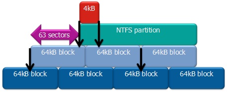
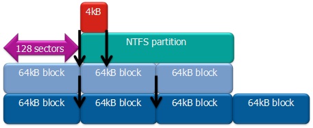
DOS Compatibility Mode
It is common for disks to have "DOS-compatible mode" enabled by default. This causes a 63 [byte]] offset to be used for the first cylinder of the first partition, leading all subsequant partitions to have the same 63 byte offset.
If you call fdisk using the -u switch, fdisk will show partition start and end positions using sectors instead of cylinders. We're more interested in sectors as we know that the sectors are 512 bytes long, and that we'll want 64 KiB making for easy math; ((64 * 1024) / 512) == 128 - Each block will have 128 sectors.
Thus, we'll want to ensure that the starting sector of all partitions sits at a position evenly divisible by 128. Using this, we can ensure that all levels of the storage stack are aligned properly.
We can see the effect of "DOS-compatible mode" by creating a partition on a new drive;
fdisk -u /dev/sdbWARNING: DOS-compatible mode is deprecated. It's strongly recommended to
switch off the mode (command 'c').Command (m for help): pDisk /dev/sdb: 30.0 GB, 30016659456 bytes
255 heads, 63 sectors/track, 3649 cylinders, total 58626288 sectors
Units = sectors of 1 * 512 = 512 bytes
Sector size (logical/physical): 512 bytes / 512 bytes
I/O size (minimum/optimal): 512 bytes / 512 bytes
Disk identifier: 0xcfeb5447
Device Boot Start End Blocks Id SystemWith "DOS-compatible mode" enabled, let's create a new partition. Notice the default initial sector number;
Command (m for help): nCommand action
e extended
p primary partition (1-4)
p
Partition number (1-4): 1
First sector (63-58626287, default 63):
Using default value 63
Last sector, +sectors or +size{K,M,G} (63-58626287, default 58626287):
Using default value 58626287Command (m for help): pDisk /dev/sdb: 30.0 GB, 30016659456 bytes
255 heads, 63 sectors/track, 3649 cylinders, total 58626288 sectors
Units = sectors of 1 * 512 = 512 bytes
Sector size (logical/physical): 512 bytes / 512 bytes
I/O size (minimum/optimal): 512 bytes / 512 bytes
Disk identifier: 0xcfeb5447
Device Boot Start End Blocks Id System
/dev/sdb1 63 58626287 29313112+ 83 LinuxNow the first partition has a starting sector of 63, which is 32,256 bytes. This will make it very difficult to create aligned LVM LVs, and thus very difficult to create aligned virtual machine storage.
Let's delete the partition, disable "DOS-compatible mode" and re-create the partiton. Note the new default start sector number.
Command (m for help): dSelected partition 1Command (m for help): cDOS Compatibility flag is not setCommand (m for help): nCommand action
e extended
p primary partition (1-4)
p
Partition number (1-4): 1
First sector (2048-58626287, default 2048):
Using default value 2048
Last sector, +sectors or +size{K,M,G} (2048-58626287, default 58626287):
Using default value 58626287Command (m for help): pDisk /dev/sdb: 30.0 GB, 30016659456 bytes
255 heads, 63 sectors/track, 3649 cylinders, total 58626288 sectors
Units = sectors of 1 * 512 = 512 bytes
Sector size (logical/physical): 512 bytes / 512 bytes
I/O size (minimum/optimal): 512 bytes / 512 bytes
Disk identifier: 0xcfeb5447
Device Boot Start End Blocks Id System
/dev/sdb1 2048 58626287 29312120 83 LinuxThis now places the starting sector as 2048, which neatly divides by 128 with no remainder. Saying it another way, the starting sector is at ((2048 * 512) / 1024) == 1,024 KiB, perfectly divisible by 64 KiB. Now everything above it will align properly.
Alignment Math
Assuming your partitions are already created, and that they were created with "DOS-compatible mode" enabled, let's look at how we can manually change the starting sector of each partition to sit on even 64 KiB boundries.
Before we can start the alignment math, we need to know how big each sector is on our hard drive. This is almost always 512 bytes, but it's still best to be sure. To check, run;
fdisk -l /dev/sda | grep SectorSector size (logical/physical): 512 bytes / 512 bytesSo now that we have confirmed our sector size, we can look at the math.
- Each 64 KiB block will use 128 sectors ((64 * 1024) / 512) == 128.
- As we create each each partition, we will be asked to enter the starting sector (using fdisk -u). Take the first free sector and divide it by 128. If it does not divide evenly, then;
- Add 127 (one sector shy of another block to guarantee we've gone past the start sector we want).
- Divide the new number by 128. This will give you a fractional number. Remove (do not round!) any number after the decimal place.
- Multiply by 128 to get the sector number we want.
Lets look at a example using real numbers. Lets say we create a new partition and the first free sector is 92807568;
92807568 ÷ 128 = 725059.125We have a remainder, so it's not on an even 64 KiB block boundry. Now we need to figure out what sector above 92807568 is evenly divisible by 128. To do that, lets add 127 (one sector shy of the next 64 KiB block), divide by 128 to get the number of 64 KiB blocks (with a remainder), remove the remainder to get an even number (do not round, you just want the bare integer), then finally multiply by 128 to get the sector number. This will give us the sector number we want our partition to start on.
92807568 + 127 = 9280769592807695 ÷ 128 = 725060.1171875int(725060.1171875) = 725060725060 x 128 = 92807680So now we know that sector number 92807680 is the first sector above 92807568 that falls on an even 64 KiB block. Now we need to alter our partition's starting sector. To do this, we will need to go into fdisk's extra functions.
| Note: Pay attention to the last sector number of each partition you create. As you create partitions, fdisk will see free space, as tiny as it is, and it will default to that as the first sector for the next partition. This is annoying. My noting the last sector of each partition you create, you can add 1 sector and do the math to find the first sector above that which sits on a 64 KiB boundary. |
Creating the Three Partitions
Here I will show you the values I entered to create the three partitions I needed on my nodes.
DO NOT COPY THIS!
The values you enter will almost certainly be different.
Start fdisk in sector mode on /dev/sda.
| Note: If you are using software RAID, you will need to do the following steps on all disks, then you can proceed to create the RAID partitions normally and they will be aligned. |
fdisk -u /dev/sdaWARNING: DOS-compatible mode is deprecated. It's strongly recommended to
switch off the mode (command 'c').Disable DOS compatibility because hey, it's not the 80s any more.
Command (m for help): cDOS Compatibility flag is not setLets take a look at the current partition layout.
Command (m for help): pDisk /dev/sda: 500.1 GB, 500107862016 bytes
255 heads, 63 sectors/track, 60801 cylinders, total 976773168 sectors
Units = sectors of 1 * 512 = 512 bytes
Sector size (logical/physical): 512 bytes / 512 bytes
I/O size (minimum/optimal): 512 bytes / 512 bytes
Disk identifier: 0x00056856
Device Boot Start End Blocks Id System
/dev/sda1 * 2048 526335 262144 83 Linux
/dev/sda2 526336 84412415 41943040 83 Linux
/dev/sda3 84412416 92801023 4194304 82 Linux swap / SolarisPerfect. Now let's create a new extended partition that will use the rest of the disk. We don't care if this is aligned so we'll just accept the default start and end sectors.
Command (m for help): nCommand action
e extended
p primary partition (1-4)eSelected partition 4
First sector (92801024-976773167, default 92801024):Just press <enter>.
Using default value 92801024
Last sector, +sectors or +size{K,M,G} (92801024-976773167, default 976773167):
Just press <enter> again.
Using default value 976773167Now we'll create the first partition. This will be a 20GB partition used by the shared GFS2 partition. As it will never host a VM, I don't care if it is aligned.
Command (m for help): nFirst sector (92803072-976773167, default 92803072):Just press <enter>.
Using default value 92803072Last sector, +sectors or +size{K,M,G} (92803072-976773167, default 976773167): +20GNow we will create the last two partitions that will host our VMs. I want to split the remaining space in half, so I need to do a little bit more math before I can proceed. I will need to see how many sectors are still free, divide by two to get the number of sectors in half the remaining free space, the add the number of already-used sectors so that I know where the first partition should end. We'll do this math in just a moment.
So let's print the current partition layout:
Command (m for help): pDisk /dev/sda: 500.1 GB, 500107862016 bytes
255 heads, 63 sectors/track, 60801 cylinders, total 976773168 sectors
Units = sectors of 1 * 512 = 512 bytes
Sector size (logical/physical): 512 bytes / 512 bytes
I/O size (minimum/optimal): 512 bytes / 512 bytes
Disk identifier: 0x00056856
Device Boot Start End Blocks Id System
/dev/sda1 * 2048 526335 262144 83 Linux
/dev/sda2 526336 84412415 41943040 83 Linux
/dev/sda3 84412416 92801023 4194304 82 Linux swap / Solaris
/dev/sda4 92801024 976773167 441986072 5 Extended
/dev/sda5 92803072 134746111 20971520 83 LinuxStart to create the new partition. Before be can sort out the last sector, we first need to find the first sector.
Command (m for help): nFirst sector (134748160-976773167, default 134748160):Now I see that it the first free sector is 134748160. I divide this by 128 and I get 1052720. It is an even number, so I don't need to do anything more as it is already on a 64 KiB boundry! So I can just press <enter> to accept it.
Using default value 134748160
Last sector, +sectors or +size{K,M,G} (134748160-976773167, default 976773167):
Now we need to do the math to find what sector marks half of the remaining free space. Let's gather some numbers;
- This partition started at sector 134748160
- The default end sector is 976773167
- That means that there are currently (976773167 - 134748160) == 842025007 sectors free.
- Half of that is (842025007 / 2) == int(421012503.5) == 421012503 sectors free (int() simply means to take the remainder off the number).
- So if we want a partition that is 421012503 long, we need to add the start sector to get our offset. That is, (421012503 + 134748160) == 555760663. This is what we will enter now.
Last sector, +sectors or +size{K,M,G} (134748160-976773167, default 976773167): 555760663Now to create the last partition, we will repeat the steps above.
Command (m for help): nFirst sector (555762712-976773167, default 555762712):Let's make sure that 555762712 is on a 64 KiB boundry;
- (555762712 / 128) == 4341896.1875 is not an even number, so we need to find the next sector on an even boundary.
- Add 127 sectors and divide by 128 again;
- (555762712 + 127) == 555762839
- (555762839 / 128) == int(4341897.1796875) == 4341897
- (4341897 * 128) == 555762816
- Now we know that we want our start sector to be 555762816.
First sector (555762712-976773167, default 555762712): 555762816Last sector, +sectors or +size{K,M,G} (555762816-976773167, default 976773167):This is the last partition, so we can just press <enter> to get the last sector on the disk.
Using default value 976773167Lets take a final look at the new partition before committing the changes to disk.
Command (m for help): pDisk /dev/sda: 500.1 GB, 500107862016 bytes
255 heads, 63 sectors/track, 60801 cylinders, total 976773168 sectors
Units = sectors of 1 * 512 = 512 bytes
Sector size (logical/physical): 512 bytes / 512 bytes
I/O size (minimum/optimal): 512 bytes / 512 bytes
Disk identifier: 0x00056856
Device Boot Start End Blocks Id System
/dev/sda1 * 2048 526335 262144 83 Linux
/dev/sda2 526336 84412415 41943040 83 Linux
/dev/sda3 84412416 92801023 4194304 82 Linux swap / Solaris
/dev/sda4 92801024 976773167 441986072 5 Extended
/dev/sda5 92803072 134746111 20971520 83 Linux
/dev/sda6 134748160 555760663 210506252 83 Linux
/dev/sda7 555762816 976773167 210505176 83 LinuxPerfect. If you divide partition six or seven's start sector by 128, you will see that both have no remainder which means that they are, if fact, aligned. This is the last time we need to worry about alignment because LVM uses an even multiple of 64 KiB in it's extent sizes, so all normal extent sized will always produce LVs on even 64 KiB boudaries.
So now write out the changes, re-probe the disk (or reboot) and then repeat all these steps on the other node.
Command (m for help): wThe partition table has been altered!
Calling ioctl() to re-read partition table.
WARNING: Re-reading the partition table failed with error 16: Device or resource busy.
The kernel still uses the old table. The new table will be used at
the next reboot or after you run partprobe(8) or kpartx(8)
Syncing disks.No reprobe using partprobe.
partprobe /dev/sdaWarning: WARNING: the kernel failed to re-read the partition table on /dev/sda
(Device or resource busy). As a result, it may not reflect all of your changes
until after reboot.In my case, the probe failed so I will reboot. To do this most safely, stop the cluster before calling reboot.
/etc/init.d/cman stopStopping cluster:
Leaving fence domain... [ OK ]
Stopping gfs_controld... [ OK ]
Stopping dlm_controld... [ OK ]
Stopping fenced... [ OK ]
Stopping cman... [ OK ]
Waiting for corosync to shutdown: [ OK ]
Unloading kernel modules... [ OK ]
Unmounting configfs... [ OK ]Now reboot.
rebootConfiguring DRBD
DRBD is configured in two parts;
- Global and common configuration options
- Resource configurations
We will be creating three separate DRBD resources, so we will create three separate resource configuration files. More on that in a moment.
Configuring DRBD Global and Common Options
The first file to edit is /etc/drbd.d/global_common.conf. In this file, we will set global configuration options and set default resource configuration options. These default resource options can be overwritten in the actual resource files which we'll create once we're done here.
cp /etc/drbd.d/global_common.conf /etc/drbd.d/global_common.conf.orig
vim /etc/drbd.d/global_common.conf
diff -u  /etc/drbd.d/global_common.conf.orig /etc/drbd.d/global_common.conf
--- /etc/drbd.d/global_common.conf.orig 2011-09-14 14:03:56.364566109 -0400
+++ /etc/drbd.d/global_common.conf 2011-09-14 14:23:37.287566400 -0400
@@ -15,24 +15,81 @@
# out-of-sync "/usr/lib/drbd/notify-out-of-sync.sh root";
# before-resync-target "/usr/lib/drbd/snapshot-resync-target-lvm.sh -p 15 -- -c 16k";
# after-resync-target /usr/lib/drbd/unsnapshot-resync-target-lvm.sh;
+
+ # This script is a wrapper for RHCS's 'fence_node' command line
+ # tool. It will call a fence against the other node and return
+ # the appropriate exit code to DRBD.
+ fence-peer "/sbin/obliterate-peer.sh";
}
startup {
# wfc-timeout degr-wfc-timeout outdated-wfc-timeout wait-after-sb
+
+ # This tells DRBD to promote both nodes to Primary on start.
+ become-primary-on both;
+
+ # This tells DRBD to wait five minutes for the other node to
+ # connect. This should be longer than it takes for cman to
+ # timeout and fence the other node *plus* the amount of time it
+ # takes the other node to reboot. If you set this too short,
+ # you could corrupt your data. If you want to be extra safe, do
+ # not use this at all and DRBD will wait for the other node
+ # forever.
+ wfc-timeout 300;
+
+ # This tells DRBD to wait for the other node for three minutes
+ # if the other node was degraded the last time it was seen by
+ # this node. This is a way to speed up the boot process when
+ # the other node is out of commission for an extended duration.
+ degr-wfc-timeout 120;
}
disk {
# on-io-error fencing use-bmbv no-disk-barrier no-disk-flushes
# no-disk-drain no-md-flushes max-bio-bvecs
+
+ # This tells DRBD to block IO and fence the remote node (using
+ # the 'fence-peer' helper) when connection with the other node
+ # is unexpectedly lost. This is what helps prevent split-brain
+ # condition and it is incredible important in dual-primary
+ # setups!
+ fencing resource-and-stonith;
}
net {
# sndbuf-size rcvbuf-size timeout connect-int ping-int ping-timeout max-buffers
# max-epoch-size ko-count allow-two-primaries cram-hmac-alg shared-secret
# after-sb-0pri after-sb-1pri after-sb-2pri data-integrity-alg no-tcp-cork
+
+ # This tells DRBD to allow two nodes to be Primary at the same
+ # time. It is needed when 'become-primary-on both' is set.
+ allow-two-primaries;
+
+ # The following three commands tell DRBD how to react should
+ # our best efforts fail and a split brain occurs. You can learn
+ # more about these options by reading the drbd.conf man page.
+ # NOTE! It is not possible to safely recover from a split brain
+ # where both nodes were primary. This care requires human
+ # intervention, so 'disconnect' is the only safe policy.
+ after-sb-0pri discard-zero-changes;
+ after-sb-1pri discard-secondary;
+ after-sb-2pri disconnect;
}
syncer {
# rate after al-extents use-rle cpu-mask verify-alg csums-alg
+
+ # This alters DRBD's default syncer rate. Note that is it
+ # *very* important that you do *not* configure the syncer rate
+ # to be too fast. If it is too fast, it can significantly
+ # impact applications using the DRBD resource. If it's set to a
+ # rate higher than the underlying network and storage can
+ # handle, the sync can stall completely.
+ # This should be set to ~30% of the *tested* sustainable read
+ # or write speed of the raw /dev/drbdX device (whichever is
+ # slower). In this example, the underlying resource was tested
+ # as being able to sustain roughly 60 MB/sec, so this is set to
+ # one third of that rate, 20M.
+ rate 20M;
}
}Configuring the DRBD Resources
As mentioned earlier, we are going to create three DRBD resources.
- Resource r0, which will be device /dev/drbd0, will be the shared GFS2 partition.
- Resource r1, which will be device /dev/drbd1, will provide disk space for VMs that will normally run on an-node01.
- Resource r2, which will be device /dev/drbd2, will provide disk space for VMs that will normally run on an-node02.
| Note: The reason for the two separate VM resources is to help protect against data loss in the off chance that a split-brain occurs, despite our counter-measures. As we will see later, recovering from a split brain requires discarding the changes on one side of the resource. If VMs are running on the same resource but on different nodes, this would lead to data loss. Using two resources helps prevent that scenario. |
Each resource configuration will be in it's own file saved as /etc/drbd.d/rX.res. The three of them will be pretty much the same. So let's take a look at the first GFS2 resource r0.res, then we'll just look at the changes for r1.res and r2.res. These files won't exist initially.
vim /etc/drbd.d/r0.res# This is the resource used for the shared GFS2 partition.
resource r0 {
# This is the block device path.
device /dev/drbd0;
# We'll use the normal internal metadisk (takes about 32MB/TB)
meta-disk internal;
# This is the `uname -n` of the first node
on an-node01.alteeve.com {
# The 'address' has to be the IP, not a hostname. This is the
# node's SN (bond1) IP. The port number must be unique amoung
# resources.
address 10.10.0.1:7789;
# This is the block device backing this resource on this node.
disk /dev/sda5;
}
# Now the same information again for the second node.
on an-node02.alteeve.com {
address 10.10.0.2:7789;
disk /dev/sda5;
}
}Now copy this to r1.res and edit for the an-node01 VM resource. The main differences are the resource name, r1, the block device, /dev/drbd1, the port, 7790 and the backing block devices, /dev/sda6.
cp /etc/drbd.d/r0.res /etc/drbd.d/r1.res
vim /etc/drbd.d/r1.res
# This is the resource used for VMs that will normally run on an-node01.
resource r1 {
# This is the block device path.
device /dev/drbd1;
# We'll use the normal internal metadisk (takes about 32MB/TB)
meta-disk internal;
# This is the `uname -n` of the first node
on an-node01.alteeve.com {
# The 'address' has to be the IP, not a hostname. This is the
# node's SN (bond1) IP. The port number must be unique amoung
# resources.
address 10.10.0.1:7790;
# This is the block device backing this resource on this node.
disk /dev/sda6;
}
# Now the same information again for the second node.
on an-node02.alteeve.com {
address 10.10.0.2:7790;
disk /dev/sda6;
}
}The last resource is again the same, with the same set of changes.
cp /etc/drbd.d/r1.res /etc/drbd.d/r2.res
vim /etc/drbd.d/r2.res
# This is the resource used for VMs that will normally run on an-node02.
resource r2 {
# This is the block device path.
device /dev/drbd2;
# We'll use the normal internal metadisk (takes about 32MB/TB)
meta-disk internal;
# This is the `uname -n` of the first node
on an-node01.alteeve.com {
# The 'address' has to be the IP, not a hostname. This is the
# node's SN (bond1) IP. The port number must be unique amoung
# resources.
address 10.10.0.1:7791;
# This is the block device backing this resource on this node.
disk /dev/sda7;
}
# Now the same information again for the second node.
on an-node02.alteeve.com {
address 10.10.0.2:7791;
disk /dev/sda7;
}
}The final step is to validate the configuration. This is done by running the following command;
drbdadm dump# /etc/drbd.conf
common {
protocol C;
net {
allow-two-primaries;
after-sb-0pri discard-zero-changes;
after-sb-1pri discard-secondary;
after-sb-2pri disconnect;
}
disk {
fencing resource-and-stonith;
}
syncer {
rate 20M;
}
startup {
wfc-timeout 300;
degr-wfc-timeout 120;
become-primary-on both;
}
handlers {
pri-on-incon-degr "/usr/lib/drbd/notify-pri-on-incon-degr.sh; /usr/lib/drbd/notify-emergency-reboot.sh; echo b > /proc/sysrq-trigger ; reboot -f";
pri-lost-after-sb "/usr/lib/drbd/notify-pri-lost-after-sb.sh; /usr/lib/drbd/notify-emergency-reboot.sh; echo b > /proc/sysrq-trigger ; reboot -f";
local-io-error "/usr/lib/drbd/notify-io-error.sh; /usr/lib/drbd/notify-emergency-shutdown.sh; echo o > /proc/sysrq-trigger ; halt -f";
fence-peer /sbin/obliterate-peer.sh;
}
}
# resource r0 on an-node01.alteeve.com: not ignored, not stacked
resource r0 {
on an-node01.alteeve.com {
device /dev/drbd0 minor 0;
disk /dev/sda5;
address ipv4 10.10.0.1:7789;
meta-disk internal;
}
on an-node02.alteeve.com {
device /dev/drbd0 minor 0;
disk /dev/sda5;
address ipv4 10.10.0.2:7789;
meta-disk internal;
}
}
# resource r1 on an-node01.alteeve.com: not ignored, not stacked
resource r1 {
on an-node01.alteeve.com {
device /dev/drbd1 minor 1;
disk /dev/sda6;
address ipv4 10.10.0.1:7790;
meta-disk internal;
}
on an-node02.alteeve.com {
device /dev/drbd1 minor 1;
disk /dev/sda6;
address ipv4 10.10.0.2:7790;
meta-disk internal;
}
}
# resource r2 on an-node01.alteeve.com: not ignored, not stacked
resource r2 {
on an-node01.alteeve.com {
device /dev/drbd2 minor 2;
disk /dev/sda7;
address ipv4 10.10.0.1:7791;
meta-disk internal;
}
on an-node02.alteeve.com {
device /dev/drbd2 minor 2;
disk /dev/sda7;
address ipv4 10.10.0.2:7791;
meta-disk internal;
}
}You'll note that the output is formatted differently, but the values themselves are the same. If there had of been errors, you would have seen them printed. Fix any problems before proceeding. Once you get a clean dump, copy the configuration over to the other node.
rsync -av /etc/drbd.d root@an-node02:/etc/sending incremental file list
drbd.d/
drbd.d/global_common.conf
drbd.d/global_common.conf.orig
drbd.d/r0.res
drbd.d/r1.res
drbd.d/r2.res
sent 7619 bytes received 129 bytes 15496.00 bytes/sec
total size is 7946 speedup is 1.03Initializing The DRBD Resources
Now that we have DRBD configured, we need to initialize the DRBD backing devices and then bring up the resources for the first time.
| Note: To save a bit of time and typing, the following sections will use a little bash magic. When commands need to be run on all three resources, rather than running the same command three times with the different resource names, we will use the short-hand form r{0,1,2} or r{0..2}. |
On both nodes, create the new metadata on the backing devices. You may need to type yes to confirm the action if any data is seen. If DRBD sees an actual file system, it will error and insist that you clear the partition. You can do this by running; dd if=/dev/zero of=/dev/sdaX bs=4M count=1000, where X is the partition you want to clear.
drbdadm create-md r{0..2}md_offset 21474832384
al_offset 21474799616
bm_offset 21474144256
Found some data
==> This might destroy existing data! <==
Do you want to proceed?[need to type 'yes' to confirm] yesWriting meta data...
initializing activity log
NOT initialized bitmap
New drbd meta data block successfully created.
success
md_offset 215558397952
al_offset 215558365184
bm_offset 215551782912
Found some data
==> This might destroy existing data! <==
Do you want to proceed?[need to type 'yes' to confirm] yesWriting meta data...
initializing activity log
NOT initialized bitmap
New drbd meta data block successfully created.
success
md_offset 215557296128
al_offset 215557263360
bm_offset 215550681088
Found some data
==> This might destroy existing data! <==
Do you want to proceed?[need to type 'yes' to confirm] yesWriting meta data...
initializing activity log
NOT initialized bitmap
New drbd meta data block successfully created.
successBefore you go any further, we'll need to load the drbd kernel module. Note that you won't normally need to do this. Later, after we get everything running the first time, we'll be able to start and stop the DRBD resources using the /etc/init.d/drbd script, which loads and unloads the drbd kernel module as needed.
modprobe drbdNow go back to the terminal windows we had used to watch the cluster start. We now want to watch the output of cat /proc/drbd so we can keep tabs on the current state of the DRBD resources. We'll do this by using the watch program, which will refresh the output of the cat call every couple of seconds.
watch cat /proc/drbdversion: 8.3.11 (api:88/proto:86-96)
GIT-hash: 0de839cee13a4160eed6037c4bddd066645e23c5 build by dag@Build64R6, 2011-08-08 08:54:05Back in the first terminal, we need to attach the backing device, /dev/sda{5..7} to their respective DRBD resources, r{0..2}. After running the following command, you will see no output on the first terminal, but the second terminal's /proc/drbd should update.
drbdadm attach r{0..2}version: 8.3.11 (api:88/proto:86-96)
GIT-hash: 0de839cee13a4160eed6037c4bddd066645e23c5 build by dag@Build64R6, 2011-08-08 08:54:05
0: cs:StandAlone ro:Secondary/Unknown ds:Inconsistent/DUnknown r----s
ns:0 nr:0 dw:0 dr:0 al:0 bm:0 lo:0 pe:0 ua:0 ap:0 ep:1 wo:b oos:20970844
1: cs:StandAlone ro:Secondary/Unknown ds:Inconsistent/DUnknown r----s
ns:0 nr:0 dw:0 dr:0 al:0 bm:0 lo:0 pe:0 ua:0 ap:0 ep:1 wo:b oos:210499788
2: cs:StandAlone ro:Secondary/Unknown ds:Inconsistent/DUnknown r----s
ns:0 nr:0 dw:0 dr:0 al:0 bm:0 lo:0 pe:0 ua:0 ap:0 ep:1 wo:b oos:210498712Take note of the connection state, cs:StandAlone, the current role, ro:Secondary/Unknown and the disk state, ds:Inconsistent/DUnknown. This tells us that our resources are not talking to one another, are not usable because they are in the Secondary state (you can't even read the /dev/drbdX device) and that the backing device does not have an up to date view of the data.
This all makes sense of course, as the resources are brand new.
So the next step is to connect the two nodes together. As before, we won't see any output from the first terminal, but the second terminal will change.
| Note: After running the following command on the first node, it's connection state will become cs:WFConnection which means that it is waiting for a connection from the other node. |
drbdadm connect r{0..2}version: 8.3.11 (api:88/proto:86-96)
GIT-hash: 0de839cee13a4160eed6037c4bddd066645e23c5 build by dag@Build64R6, 2011-08-08 08:54:05
0: cs:Connected ro:Secondary/Secondary ds:Inconsistent/Inconsistent C r-----
ns:0 nr:0 dw:0 dr:0 al:0 bm:0 lo:0 pe:0 ua:0 ap:0 ep:1 wo:b oos:20970844
1: cs:Connected ro:Secondary/Secondary ds:Inconsistent/Inconsistent C r-----
ns:0 nr:0 dw:0 dr:0 al:0 bm:0 lo:0 pe:0 ua:0 ap:0 ep:1 wo:b oos:210499788
2: cs:Connected ro:Secondary/Secondary ds:Inconsistent/Inconsistent C r-----
ns:0 nr:0 dw:0 dr:0 al:0 bm:0 lo:0 pe:0 ua:0 ap:0 ep:1 wo:b oos:210498712We can now see that the two nodes are talking to one another properly as the connection state has changed to cs:Connected. They can see that their peer node is in the same state as they are; Secondary/Inconsistent.
Seeing as the resources are brand new, there is no data to synchronize or save. So we're going to issue a special command that will only ever be used this one time. It will tell DRBD to immediately consider the DRBD resources to be up to date.
On one node only, run;
drbdadm -- --clear-bitmap new-current-uuid r{0..2}As before, look to the second terminal to see the new state of affairs.
version: 8.3.11 (api:88/proto:86-96)
GIT-hash: 0de839cee13a4160eed6037c4bddd066645e23c5 build by dag@Build64R6, 2011-08-08 08:54:05
0: cs:Connected ro:Secondary/Secondary ds:UpToDate/UpToDate C r-----
ns:0 nr:0 dw:0 dr:0 al:0 bm:0 lo:0 pe:0 ua:0 ap:0 ep:1 wo:b oos:0
1: cs:Connected ro:Secondary/Secondary ds:UpToDate/UpToDate C r-----
ns:0 nr:0 dw:0 dr:0 al:0 bm:0 lo:0 pe:0 ua:0 ap:0 ep:1 wo:b oos:0
2: cs:Connected ro:Secondary/Secondary ds:UpToDate/UpToDate C r-----
ns:0 nr:0 dw:0 dr:0 al:0 bm:0 lo:0 pe:0 ua:0 ap:0 ep:1 wo:b oos:0Voila!
We could promote both sides to Primary by running drbdadm primary r{0..2} on both nodes, but there is no purpose in doing that at this stage as we can safely say our DRBD is ready to go. So instead, let's just stop DRBD entirely. We'll also prevent it from starting on boot as drbd will be managed by the cluster in a later step.
On both nodes run;
chkconfig drbd off
/etc/init.d/drbd stop
Stopping all DRBD resources: .The second terminal will start complaining that /proc/drbd no longer exists. This is because the drbd init script unloaded the drbd kernel module. It is expected and not a problem.
Configuring Clustered Storage
Before we can provision the first virtual machine, we must first create the storage that will back them. This will take a few steps;
- Configuring LVM's clustered locking and creating the PVs, VGs and LVs
- Formatting and configuring the shared GFS2 partition.
- Adding storage to the cluster's resource management.
Clustered Logical Volume Management
We will assign all three DRBD resources to be managed by clustered LVM. This isn't strictly needed for the GFS2 partition, as it uses DLM directly. However, the flexibility of LVM is very appealing, and will make later growth of the GFS2 partition quite trivial, should the need arise.
The real reason for clustered LVM in our cluster is to provide DLM-backed locking to the partitions, or logical volumes in LVM, that will be used to back our VMs. Of course, the flexibility of LVM managed storage is enough of a win to justify using LVM for our VMs in itself, and shouldn't be ignored here.
Configuring Clustered LVM Locking
Before we create the clustered LVM, we need to first make three changes to the LVM configuration.
- We need to filter out the DRBD backing devices so that LVM doesn't see the same signature twice.
- Switch from local locking to clustered locking.
- Prevent fall-back to local locking when the cluster is not available.
The configuration option to filter out the DRBD backing device is, surprisingly, filter = [ ... ]. By default, it is set to allow everything via the "a/.*/" regular expression. We're only using DRBD in our LVM, so we're going to flip that to reject everything except DRBD by changing the regex to "a|/dev/drbd*|", "r/.*/". If we didn't do this, LVM would see the same signature on the DRBD device and again on the backing devices, at which time it would ignore the DRBD device. This filter allows LVM to only inspect the DRBD devices for LVM signatures.
For the locking, we're going to change the locking_type from 1 (local locking) to 3, (clustered locking).
We're also going to disallow fall-back to local locking. Normally, LVM would try to access a clustered LVM VG using local locking if DLM is not available. We want to prevent any access to the clustered LVM volumes except when the cluster is itself running. This is done by changing fallback_to_local_locking to 0.
cp /etc/lvm/lvm.conf /etc/lvm/lvm.conf.orig
vim /etc/lvm/lvm.conf
diff -u /etc/lvm/lvm.conf.orig /etc/lvm/lvm.conf
--- /etc/lvm/lvm.conf.orig 2011-09-16 14:07:08.500691102 -0400
+++ /etc/lvm/lvm.conf 2011-10-10 16:28:24.530564214 -0400
@@ -50,7 +50,8 @@
# By default we accept every block device:
- filter = [ "a/.*/" ]
+ #filter = [ "a/.*/" ]
+ filter = [ "a|/dev/drbd*|", "r/.*/" ]
# Exclude the cdrom drive
# filter = [ "r|/dev/cdrom|" ]
@@ -278,7 +279,8 @@
# Type 3 uses built-in clustered locking.
# Type 4 uses read-only locking which forbids any operations that might
# change metadata.
- locking_type = 1
+ #locking_type = 1
+ locking_type = 3
# Set to 0 to fail when a lock request cannot be satisfied immediately.
wait_for_locks = 1
@@ -294,7 +296,7 @@
# to 1 an attempt will be made to use local file-based locking (type 1).
# If this succeeds, only commands against local volume groups will proceed.
# Volume Groups marked as clustered will be ignored.
- fallback_to_local_locking = 1
+ fallback_to_local_locking = 0
# Local non-LV directory that holds file-based locks while commands are
# in progress. A directory like /tmp that may get wiped on reboot is OK.Copy the modified lvm.conf file to the other node.
rsync -av /etc/lvm/lvm.conf root@an-node02:/etc/lvm/sending incremental file list
lvm.conf
sent 200 bytes received 223 bytes 282.00 bytes/sec
total size is 21809 speedup is 51.56Starting the clvmd Daemon
A little later on, we're going to put clustered LVM under the control of rgmanager. Before we can do that though, we need to start it manually so that we can use it to create the LV that will back the GFS2 /shared partition, which we will also be adding to rgmanager when we build our storage services.
Before we start the clvmd daemon, we'll want to ensure that the cluster is running.
cman_tool statusVersion: 6.2.0
Config Version: 8
Cluster Name: an-clusterA
Cluster Id: 29382
Cluster Member: Yes
Cluster Generation: 164
Membership state: Cluster-Member
Nodes: 2
Expected votes: 1
Total votes: 2
Node votes: 1
Quorum: 1
Active subsystems: 7
Flags: 2node
Ports Bound: 0
Node name: an-node01.alteeve.com
Node ID: 1
Multicast addresses: 239.192.114.57
Node addresses: 10.20.0.1It is, and both nodes are members. We can start the clvmd daemon now.
/etc/init.d/clvmd startStarting clvmd:
Activating VG(s): No volume groups found
[ OK ]We've not created any clustered volume groups yet, so that is expected.
| Note: At this stage, the cluster does not start at boot, so we can't start clvmd at boot yet, either. We'll do this at the end of the tutorial, so for now, disable clvmd and start it manually after starting cman when you first start your cluster. |
chkconfig clvmd off
chkconfig --list clvmd
clvmd 0:off 1:off 2:off 3:off 4:off 5:off 6:offInitialize Out DRBD Resource For Use As LVM PVs
| Note: Fix: At this point, the user has been told to stop drbd and clvmd... |
Before we can use LVM, clustered or otherwise, we need to initialize one or more raw storage devices. This is done using the pvcreate command.
First though, we need to make sure that they are up and Primary/Primary on both nodes.
/etc/init.d/drbd statusdrbd driver loaded OK; device status:
version: 8.3.11 (api:88/proto:86-96)
GIT-hash: 0de839cee13a4160eed6037c4bddd066645e23c5 build by dag@Build64R6, 2011-08-08 08:54:05
m:res cs ro ds p mounted fstype
0:r0 Connected Primary/Primary UpToDate/UpToDate C
1:r1 Connected Primary/Primary UpToDate/UpToDate C
2:r2 Connected Primary/Primary UpToDate/UpToDate CAll three resources are up on both nodes, so we can initilize our resources. We're going to do this on an-node01, then run pvscan on an-node02. We should see the newly initialized DRBD resources appear.
Running pvscan first, we'll see that no PVs have been created.
pvscan No matching physical volumes foundOn an-node01, initialize the PVs;
pvcreate /dev/drbd{0..2} Physical volume "/dev/drbd0" successfully created
Physical volume "/dev/drbd1" successfully created
Physical volume "/dev/drbd2" successfully createdOn both nodes, re-run pvscan and the new PVs should show. This works because DRBD is keeping the data in sync, including the new LVM signatures.
pvscan PV /dev/drbd0 lvm2 [20.00 GiB]
PV /dev/drbd1 lvm2 [200.75 GiB]
PV /dev/drbd2 lvm2 [200.75 GiB]
Total: 3 [421.49 GiB] / in use: 0 [0 ] / in no VG: 3 [421.49 GiB]Done.
Creating Cluster Volume Groups
As with initializing the DRBD resource above, we will create out volume groups, VGs, on an-node01 only, but we will then see them on both nodes.
Check to confirm that no VGs exist;
vgdisplay No volume groups foundNow to create the VGs, we'll use the vgcreate command with the -c y switch, which tells LVM to make the VG a clustered VG. Note that when the clvmd daemon is running, -c y is implied. However, I like to get into the habit of using it because it will trigger an error if, for some reason, clvmd wasn't actually running.
On an-node01, create the three VGs.
- VG for the GFS2 /shared partition;
vgcreate -c y shared-vg0 /dev/drbd0 Clustered volume group "shared-vg0" successfully created- VG for the VMs that will primarily run on an-node01;
vgcreate -c y an01-vg0 /dev/drbd1 Clustered volume group "an01-vg0" successfully created- VG for the VMs that will primarily run on an-node02;
vgcreate -c y an02-vg0 /dev/drbd2 Clustered volume group "an02-vg0" successfully createdNow on both nodes, we should see the three new volume groups.
vgscan Reading all physical volumes. This may take a while...
Found volume group "an02-vg0" using metadata type lvm2
Found volume group "an01-vg0" using metadata type lvm2
Found volume group "shared-vg0" using metadata type lvm2Creating a Logical Volume
At this stage, we're going to create only one LV for the GFS2 partition. We'll create the rest later when we're ready to provision the VMs. This will be the /shared partiton, which we will discuss further in the next section.
As before, we'll create the LV on an-node01 and then verify it exists on both nodes.
Before we create our first LV, check lvscan.
lvscanNothing is returned.
On an-node01, create the the LV on the shared-vg0 VG, using all of the available space.
lvcreate -l 100%FREE -n shared shared-vg0 Logical volume "shared" createdNow on both nodes, check that the new LV exists.
lvscan ACTIVE '/dev/shared-vg0/shared' [20.00 GiB] inheritPerfect. We can now create our GFS2 partition.
The GFS2-formatted /shared partition will be used for four main purposes;
- /shared/files; Storing files like ISO images needed when provisioning VMs.
- /shared/provision; Storing short scripts used to call virt-install which handles the creation of our VMs.
- /shared/definitions; This is where the XML definition files which define the emulated hardware backing our VMs are kept. This is the most critical directory as the cluster will look here when starting and recovering VMs.
- /shared/archive; This is used to store old copies of the XML definition files. I like to make a time-stamped copy of definition files prior to altering and redefining a VM. This way, I can quickly and easily revert to an old configuration should I run into trouble.
Make sure that both drbd and clvmd are running.
The mkfs.gfs2 call uses a few switches that are worth explaining;
- -p lock_dlm; This tells GFS2 to use DLM for it's clustered locking. Currently, this is the only supported locking type.
- -j 2; This tells GFS2 to create two journals. This must match the number of nodes that will try to mount this partition at any one time.
- -t an-clusterA:shared; This is the lockspace name, which must be in the format <clustename>:<fsname>. The clustername must match the one in cluster.conf, and any node that belongs to a cluster of another name will not be allowed to access the file system.
| Note: Depending on the size of the new partition, this call could take a while to complete. Please be patient. |
Then, on an-node01, run;
mkfs.gfs2 -p lock_dlm -j 2 -t an-clusterA:shared /dev/shared-vg0/sharedThis will destroy any data on /dev/shared-vg0/shared.
It appears to contain: symbolic link to `../dm-0'
Are you sure you want to proceed? [y/n] y
Device: /dev/shared-vg0/shared
Blocksize: 4096
Device Size 20.00 GB (5241856 blocks)
Filesystem Size: 20.00 GB (5241855 blocks)
Journals: 2
Resource Groups: 80
Locking Protocol: "lock_dlm"
Lock Table: "an-clusterA:shared"
UUID: 2A96F8AA-664F-84CA-9147-85B53215D911On both nodes, run all of the following commands.
mkdir /shared
mount /dev/shared-vg0/shared /shared/Confirm that /shared is now mounted.
df -hP /sharedFilesystem Size Used Avail Use% Mounted on
/dev/mapper/shared--vg0-shared 20G 259M 20G 2% /sharedNote that the path under Filesystem is different from what we used when creating the GFS2 partition. This is an effect of Device Mapper, which is used by LVM to create symlinks to actual block device paths. If we look at our /dev/shared-vg0/shared device and the device from df, /dev/mapper/shared--vg0-shared, we'll see that they both point to the same actual block device.
ls -lah /dev/shared-vg0/shared /dev/mapper/shared--vg0-sharedlrwxrwxrwx 1 root root 7 Oct 23 16:35 /dev/mapper/shared--vg0-shared -> ../dm-0
lrwxrwxrwx 1 root root 7 Oct 23 16:35 /dev/shared-vg0/shared -> ../dm-0ls -lah /dev/dm-0brw-rw---- 1 root disk 253, 0 Oct 23 16:35 /dev/dm-0This next command is a bit of command-line voodoo. It takes the output from gfs2_edit -p sb /dev/shared-vg0/shared, grep's out the UUID line for the new GFS2 partition, parses out of that the UUID itself, converts it to lower-case and, finally, spits out a string that can be used in /etc/fstab. We'll run it twice; The first time to confirm that the output is what we expect and the second time to append it to /etc/fstab.
The gfs2 daemon can only work on GFS2 partitions that have been defined in fstab, so this is a required step on both nodes.
We use rw,suid,dev,exec,nouser,async instead of default because we do not want the auto option, which is implied by default. With auto, the operating system would try to mount the GFS2 filesystem at boot, which would fail as the cluster isn't up. This failure would drop the operating system to single-user mode. There are other ways of avoiding this problem, like using noauto or _netdev. Feel free to use which ever option you prefer, so long as the OS doesn't attempt to mount this partition on boot.
echo `gfs2_edit -p sb /dev/shared-vg0/shared | grep sb_uuid | sed -e "s/.*sb_uuid *\(.*\)/UUID=\L\1\E \/shared\t\tgfs2\trw,suid,dev,exec,nouser,async\t0 0/"`UUID=2a96f8aa-664f-84ca-9147-85b53215d911 /shared gfs2 rw,suid,dev,exec,nouser,async 0 0This looks good, so now re-run it but redirect the output to append to /etc/fstab. We'll confirm it worked by checking the status of the gfs2 daemon.
echo `gfs2_edit -p sb /dev/shared-vg0/shared | grep sb_uuid | sed -e "s/.*sb_uuid *\(.*\)/UUID=\L\1\E \/shared\t\tgfs2\trw,suid,dev,exec,nouser,async\t0 0/"` >> /etc/fstab
/etc/init.d/gfs2 statusConfigured GFS2 mountpoints:
/shared
Active GFS2 mountpoints:
/sharedOn an-node01
mkdir /shared/{definitions,provision,archive,files}On both nodes, confirm that all of the new directories exist and are visible.
ls -lah /shared/total 24K
drwxr-xr-x 6 root root 3.8K Oct 23 16:53 .
dr-xr-xr-x. 26 root root 4.0K Oct 23 11:28 ..
drwxr-xr-x 2 root root 0 Oct 23 16:53 archive
drwxr-xr-x 2 root root 0 Oct 23 16:53 definitions
drwxr-xr-x 2 root root 0 Oct 23 16:53 files
drwxr-xr-x 2 root root 0 Oct 23 16:53 provisionWounderful!
Stopping All Clustered Storage Components
Before we can the clustered storage under the cluster's control, we need to stop the services manually and then insure they won't try to start on boot.
On both nodes, run;
/etc/init.d/gfs2 stop && /etc/init.d/clvmd stop && /etc/init.d/drbd stopUnmounting GFS2 filesystem (/shared): [ OK ]
Deactivating clustered VG(s): 0 logical volume(s) in volume group "an02-vg0" now active
0 logical volume(s) in volume group "an01-vg0" now active
0 logical volume(s) in volume group "shared-vg0" now active
[ OK ]
Signaling clvmd to exit [ OK ]
clvmd terminated [ OK ]
Stopping all DRBD resources:Make sure that the three daemons are not going to start on boot.
chkconfig gfs2 off && chkconfig clvmd off && chkconfig drbd off
chkconfig --list |grep -e gfs2 -e clvmd -e drbdclvmd 0:off 1:off 2:off 3:off 4:off 5:off 6:off
drbd 0:off 1:off 2:off 3:off 4:off 5:off 6:off
gfs2 0:off 1:off 2:off 3:off 4:off 5:off 6:offManaging Storage In The Cluster
A little while back, we spoke about how the cluster is split into two components; cluster communication managed by cman and resource management provided by rgmanager. It's the later which we will now configure.
In the cluster.conf, the rgmanager component is contained within the <rm /> element tags. Within this element are three types of child elements. They are:
- Failover Domains - <failoverdomains />;
- There are optional constraints which allow for control which nodes, and under what circumstances, services may run. When not used, a service will be allowed to run on any node in the cluster without constraints or ordering.
- Resources - <resources />;
- Within this element, available resources are defined. Simply having a resource here will not put it under cluster control. Rather, it makes it available for use in <service /> elements.
- Services - <service />;
- This element contains one or more parallel or series child-elements which are themselves references to <resources /> elements. When in parallel, the services will start and stop at the same time. When in series, the services start in order and stop in reverse order. We will also see a specialized type of service that uses the <vm /> element name, as you can probably guess, for creating virtual machine services.
We'll look at each of these components in more detail shortly.
Before We Start
During the build-up of DRBD earlier, we had to reboot the servers. So let's start by making sure the cluster is up.
/etc/init.d/cman statuscorosync is stoppedIt's down, so start it and rgmanager up.
/etc/init.d/cman start && /etc/init.d/rgmanager startStarting cluster:
Checking if cluster has been disabled at boot... [ OK ]
Checking Network Manager... [ OK ]
Global setup... [ OK ]
Loading kernel modules... [ OK ]
Mounting configfs... [ OK ]
Starting cman... [ OK ]
Waiting for quorum... [ OK ]
Starting fenced... [ OK ]
Starting dlm_controld... [ OK ]
Starting gfs_controld... [ OK ]
Unfencing self... [ OK ]
Joining fence domain... [ OK ]
Starting Cluster Service Manager: [ OK ]Confirm everything is up.
cman_tool statusVersion: 6.2.0
Config Version: 8
Cluster Name: an-clusterA
Cluster Id: 29382
Cluster Member: Yes
Cluster Generation: 180
Membership state: Cluster-Member
Nodes: 2
Expected votes: 1
Total votes: 2
Node votes: 1
Quorum: 1
Active subsystems: 8
Flags: 2node
Ports Bound: 0 177
Node name: an-node01.alteeve.com
Node ID: 1
Multicast addresses: 239.192.114.57
Node addresses: 10.20.0.1Perfect, let's proceed.
A Note On Daemon Starting
There are four daemons we will be putting under cluster control;
- drbd; Replicated storage.
- clvmd; Clustered LVM.
- gfs2; Mounts and Unmounts configured GFS2 partition.
- libvirtd; Provides access to virsh and other libvirt tools. Needed for running our VMs.
The reason we do not want to start these daemons with the system is so that we can let the cluster do it. This way, should any fail, the cluster will detect the failure and fail the service tree properly. For example, lets say that drbd failed to start, rgmanager would fail the storage service and give up, rather than continue trying to start clvmd and the rest.
However, if left to boot on start, the failure of the drbd would not effect the startup of clvmd, which would then not find it's PVs given that DRBD is down. Next, the system would try to start the gfs2 daemon which would also fail as the LV backing the partition would not be available. Finally, the system would start libvirtd, which would enable the start of virtual machine, which would also be missing their "hard drives" as their backing LVs would also not be available.
Defining The Resources
Lets start by first defining our clustered resources.
As stated before, the addition of these resources does not, in itself, put the defined resources under the cluster's management. Instead, it defines services, like init.d scripts. These can then be used by one or more <service /> elements, as we will see shortly. For now, it is enough to know what, until a resource is defined, it can not be used in the cluster.
Given that this is the first component of rgmanager being added to cluster.conf, we will be creating the parent <rm /> elements here as well.
Let's take a look at the new section, then discuss the parts.
<?xml version="1.0"?>
<cluster name="an-clusterA" config_version="9">
<cman expected_votes="1" two_node="1"/>
<clusternodes>
<clusternode name="an-node01.alteeve.com" nodeid="1">
<fence>
<method name="ipmi">
<device name="ipmi_an01" action="reboot"/>
</method>
<method name="pdu2">
<device name="pdu2" port="1" action="reboot"/>
</method>
</fence>
</clusternode>
<clusternode name="an-node02.alteeve.com" nodeid="2">
<fence>
<method name="ipmi">
<device name="ipmi_an02" action="reboot"/>
</method>
<method name="pdu2">
<device name="pdu2" port="2" action="reboot"/>
</method>
</fence>
</clusternode>
</clusternodes>
<fencedevices>
<fencedevice name="ipmi_an01" agent="fence_ipmilan" ipaddr="an-node01.ipmi" login="root" passwd="secret" />
<fencedevice name="ipmi_an02" agent="fence_ipmilan" ipaddr="an-node02.ipmi" login="root" passwd="secret" />
<fencedevice agent="fence_apc_snmp" ipaddr="pdu2.alteeve.com" name="pdu2"/>
</fencedevices>
<fence_daemon post_join_delay="30"/>
<totem rrp_mode="none" secauth="off"/>
<rm log_level="5">
<resources>
<script file="/etc/init.d/drbd" name="drbd"/>
<script file="/etc/init.d/clvmd" name="clvmd"/>
<script file="/etc/init.d/gfs2" name="gfs2"/>
<script file="/etc/init.d/libvirtd" name="libvirtd"/>
</resources>
</rm>
</cluster>First and foremost; Note that we've incremented the version to 9. As always, increment and then edit.
Let's focus on the new section;
<rm log_level="5">
<resources>
<script file="/etc/init.d/drbd" name="drbd"/>
<script file="/etc/init.d/clvmd" name="clvmd"/>
<script file="/etc/init.d/gfs2" name="gfs2"/>
<script file="/etc/init.d/libvirtd" name="libvirtd"/>
</resources>
</rm>The new <rm log_level="5">...</rm> element tells the cluster that this is the section for rgmanager and that we're setting the log_level to 5. This log_level is slightly less verbose that the default. Specifically, by default, there is an entry in /var/log/messages every time each resource is checked. This quickly adds a lot of questionably useful information to syslog. By changing this, we will still see all important messages, but these resource check messages are surpressed. If you are ever curious about whether or not rgmanager is, in fact, checking the services than either remove log_level="5" or change it to 6 or higher.
The <resources>...</resources> element contains our four <script .../> resources. This is a particular type of resource which specificially handles that starting and stopping of init.d style scripts. That is, the script must exit with LSB compliant codes. They must also properly react to being called with the sole argument of start, stop and status.
| Note: TODO: Find (or create) proper documention for all resource scripts. |
There are many other types of resources which, with the exception of <vm .../>, we will not be looking at in this tutorial. Should you be interested in them, please look in /usr/share/cluster for the various scripts (executable files that end with .sh).
Each of our four <script ... /> resources have two attributes;
- file="..."; The full path to the script to be managed.
- name="..."; A unique name used to reference this resource later on in the <service /> elements.
Other resources are more involved, but the <script .../> resources are quite simple.
Creating Failover Domains
Failover domains are, at their most basic, a collection of one or more nodes in the cluster with a particular set of rules associated with them. Services can then be configured to operate within the context of a given failover domain. There are a few key options to be aware of.
Failover domains are optional and can be left out of the cluster, generally speaking. However, in our cluster, we will need them for our storage services, as we will later see, so please do not skip this step.
- A failover domain can be unordered or prioritized.
- When unordered, a service will start on any node in the domain. Should that node later fail, it will restart to another random node in the domain.
- When prioritized, a service will start on the available node with the highest priority in the domain. Should that node later fail, the service will restart on the available node with the next highest priority.
- A failover domain can be restricted or unrestricted.
- When restricted, a service is only allowed to start on, or restart on. a nodes in the domain. When no nodes are available, the service will be stopped.
- When unrestricted, a service will try to start on, or restart on, a node in the domain. However, when no domain members are available, the cluster will pick another available node at random to start the service on.
- A failover domain can have a failback policy.
- When a domain allows for failback and the domain is ordered, and a node with a higher priority (re)joins the cluster, services within the domain will migrate to that higher-priority node. This allows for automated restoration of services on a failed node when it rejoins the cluster.
- When a domain does not allow for failback, but is unrestricted, failback of services that fell out of the domain will happen anyway. That is to say, nofailback="1" is ignored if a service was running on a node outside of the failover domain and a node within the domain joins the cluster. However, once the service is on a node within the domain, the service will not relocate to a higher-priority node should one join the cluster later.
- When a domain does not allow for failback and is restricted, then failback of services will never occur.
What we need to do at this stage is to create something of a hack. Let me explain;
As discussed earlier, we need to start a set of local daemons on all nodes. We want this to happen within the guidance of the cluster. These aren't really clustered resources though as they can only ever run on their host node. They will never be relocated or restarted elsewhere in the cluster. So to work around this desire to "cluster the unclusterable", we're going to create a failover domain for each node in the cluster. Each of these domains will have only one of the cluster nodes as members of the domain and the domain will be restricted, unordered and have no failback. With this configuration, any service group using it will only ever run on the one node in the domain.
In the next step, we will create a service group, then replicate it once for each node in the cluster. The only difference will be the failoverdomain each is set to use. With our configuration of two nodes then, we will have two failover domains, one for each node, and we will define the clustered storage service twice, each one using one of the two failover domains.
Let's look at the complete updated cluster.conf, then we will focus closer on the new section.
<?xml version="1.0"?>
<cluster name="an-clusterA" config_version="10">
<cman expected_votes="1" two_node="1"/>
<clusternodes>
<clusternode name="an-node01.alteeve.com" nodeid="1">
<fence>
<method name="ipmi">
<device name="ipmi_an01" action="reboot"/>
</method>
<method name="pdu2">
<device name="pdu2" port="1" action="reboot"/>
</method>
</fence>
</clusternode>
<clusternode name="an-node02.alteeve.com" nodeid="2">
<fence>
<method name="ipmi">
<device name="ipmi_an02" action="reboot"/>
</method>
<method name="pdu2">
<device name="pdu2" port="2" action="reboot"/>
</method>
</fence>
</clusternode>
</clusternodes>
<fencedevices>
<fencedevice name="ipmi_an01" agent="fence_ipmilan" ipaddr="an-node01.ipmi" login="root" passwd="secret" />
<fencedevice name="ipmi_an02" agent="fence_ipmilan" ipaddr="an-node02.ipmi" login="root" passwd="secret" />
<fencedevice agent="fence_apc_snmp" ipaddr="pdu2.alteeve.com" name="pdu2"/>
</fencedevices>
<fence_daemon post_join_delay="30"/>
<totem rrp_mode="none" secauth="off"/>
<rm log_level="5">
<resources>
<script file="/etc/init.d/drbd" name="drbd"/>
<script file="/etc/init.d/clvmd" name="clvmd"/>
<script file="/etc/init.d/gfs2" name="gfs2"/>
<script file="/etc/init.d/libvirtd" name="libvirtd"/>
</resources>
<failoverdomains>
<failoverdomain name="only_an01" nofailback="1" ordered="0" restricted="1">
<failoverdomainnode name="an-node01.alteeve.com"/>
</failoverdomain>
<failoverdomain name="only_an02" nofailback="1" ordered="0" restricted="1">
<failoverdomainnode name="an-node02.alteeve.com"/>
</failoverdomain>
</failoverdomains>
</rm>
</cluster>As always, the version was incremented, this time to 10. We've also added the new <failoverdomains>...</failoverdomains> element. Let's take a closer look at this new element.
<failoverdomains>
<failoverdomain name="only_an01" nofailback="1" ordered="0" restricted="1">
<failoverdomainnode name="an-node01.alteeve.com"/>
</failoverdomain>
<failoverdomain name="only_an02" nofailback="1" ordered="0" restricted="1">
<failoverdomainnode name="an-node02.alteeve.com"/>
</failoverdomain>
</failoverdomains>The first thing to node is that there are two <failoverdomain...>...</failoverdomain> child elements.
- The first has the name only_an01 and contains only the node an-node01 as a member.
- The second is effectively identical, save that the domain's name is only_an02 and it contains only the node an-node02 as a member.
The <failoverdomain ...> element has four attributes;
- The name="..." attribute sets the unique name of the domain which we will later use to bind a service to the domain.
- The nofailback="1" attribute tells the cluster to never "fail back" any services in this domain. This seems redundant, given there is only one node, but when combined with restricted="0", prevents any migration of services.
- The ordered="0" this is also somewhat redundant in that there is only one node defined in the domain, but I don't like to leave attributes undefined so I have it here.
- The restricted="1" attribute is key in that it tells the cluster to not try to restart services within this domain on any other nodes outside of the one defined in the failover domain.
Each of the <failoverdomain...> elements has a single <failoverdomainnode .../> child element. This is a very simple element which has, at this time, only one attribute;
- name="..."; The name of the node to include in the failover domain. This name must match the corresponding <clusternode name="..." node name.
At this point, we're ready to finally create our clustered services.
Creating Clustered Services
With the resources defined and the failover domains created, we can set about creating our services.
Generally speaking, services can have one or more resources within them. When two or more resources exist, then can be put into a dependency tree, they can used in parallel or a combination of parallel and dependent resources.
When you create a service dependency tree, you put each dependent resource as a child element of it's parent. The resources are then started in order, starting at the top of the tree and working it's way down to the deepest child resource. If at any time one of the resources should fail, the entire service will be declared failed and no attempt will be made to try and start any further child resources. Conversely, stopping the service will cause the deepest child resource to be stopped first. Then the second deepest and on upwards towards the top resource. This is exactly the behaviour we want, as we will see shortly.
When resources are defined in parallel, all defined resources will be started at the same time. Should any one of the resources fail to start, the entire resource will declared failed. Stopping the service will likewise cause a simultaneous call to stop all resources.
As before, let's take a look at the entire updated cluster.conf file, then we'll focus in on the new service section.
<?xml version="1.0"?>
<cluster name="an-clusterA" config_version="11">
<cman expected_votes="1" two_node="1"/>
<clusternodes>
<clusternode name="an-node01.alteeve.com" nodeid="1">
<fence>
<method name="ipmi">
<device name="ipmi_an01" action="reboot"/>
</method>
<method name="pdu2">
<device name="pdu2" port="1" action="reboot"/>
</method>
</fence>
</clusternode>
<clusternode name="an-node02.alteeve.com" nodeid="2">
<fence>
<method name="ipmi">
<device name="ipmi_an02" action="reboot"/>
</method>
<method name="pdu2">
<device name="pdu2" port="2" action="reboot"/>
</method>
</fence>
</clusternode>
</clusternodes>
<fencedevices>
<fencedevice name="ipmi_an01" agent="fence_ipmilan" ipaddr="an-node01.ipmi" login="root" passwd="secret" />
<fencedevice name="ipmi_an02" agent="fence_ipmilan" ipaddr="an-node02.ipmi" login="root" passwd="secret" />
<fencedevice agent="fence_apc_snmp" ipaddr="pdu2.alteeve.com" name="pdu2"/>
</fencedevices>
<fence_daemon post_join_delay="30"/>
<totem rrp_mode="none" secauth="off"/>
<rm log_level="5">
<resources>
<script file="/etc/init.d/drbd" name="drbd"/>
<script file="/etc/init.d/clvmd" name="clvmd"/>
<script file="/etc/init.d/gfs2" name="gfs2"/>
<script file="/etc/init.d/libvirtd" name="libvirtd"/>
</resources>
<failoverdomains>
<failoverdomain name="only_an01" nofailback="1" ordered="0" restricted="1">
<failoverdomainnode name="an-node01.alteeve.com"/>
</failoverdomain>
<failoverdomain name="only_an02" nofailback="1" ordered="0" restricted="1">
<failoverdomainnode name="an-node02.alteeve.com"/>
</failoverdomain>
</failoverdomains>
<service name="storage_an01" autostart="1" domain="only_an01" exclusive="0" recovery="restart">
<script ref="drbd">
<script ref="clvmd">
<script ref="gfs2">
<script ref="libvirtd"/>
</script>
</script>
</script>
</service>
<service name="storage_an02" autostart="1" domain="only_an02" exclusive="0" recovery="restart">
<script ref="drbd">
<script ref="clvmd">
<script ref="gfs2">
<script ref="libvirtd"/>
</script>
</script>
</script>
</service>
</rm>
</cluster>With the version now at 11, we have added two <service...>...</service> elements. Each containing a four <script ...> type resources in a service tree configuration. Let's take a closer look.
<service name="storage_an01" autostart="1" domain="only_an01" exclusive="0" recovery="restart">
<script ref="drbd">
<script ref="clvmd">
<script ref="gfs2">
<script ref="libvirtd"/>
</script>
</script>
</script>
</service>
<service name="storage_an02" autostart="1" domain="only_an02" exclusive="0" recovery="restart">
<script ref="drbd">
<script ref="clvmd">
<script ref="gfs2">
<script ref="libvirtd"/>
</script>
</script>
</script>
</service>The <service ...>...</service> elements have five attributes each;
- The name="..." attribute is a unique name that will be used to identify the service, as we will see later.
- The autostart="1" attribute tells the cluster that, when it starts, it should automatically start this service.
- The domain="..." attribute tells the cluster which failover domain this service must run within. The two otherwise identical services each point to a different failover domain, as we discussed in the previous section.
- The exclusive="0" attribute tells the cluster that a node running this service is allowed to to have other services running as well.
- The recovery="restart" attribute sets the service recovery policy. As the name implies, the cluster will try to restart this service should it fail. Should the service fail multiple times in a row, it will be disabled. The exact number of failures allowed before disabling is configurable using the optional max_restarts and restart_expire_time attributes, which are not covered here.
| Warning: It is a fairly common mistake to interpret exclusive to mean that a service is only allowed to run on one node at a time. This is not the case, please do not use this attribute incorrectly. |
Within each of the two <service ...>...</service> attributes are four <script...> type resources. These are configured as a service tree in the order;
- drbd -> clvmd -> gfs2 -> libvirtd.
Each of these <script ...> elements has just one attribute; ref="..." which points to a corresponding script resource.
The logic for this particular resource tree is;
- DRBD needs to start so that the bare clustered storage devices become available.
- Clustered LVM must next start so that the logical volumes used by GFS2 and our VMs become available.
- The GFS2 partition contains the XML definition files needed to start our virtual machines.
- Finally, libvirtd must be running for the virtual machines to be able to run. By putting this daemon in the resource tree, we can ensure that no attempt to start a VM will succeed until all of the clustered storage stack is available.
From the other direction, we need the stop order to be organized in the reverse order.
- Stopping libvirtd would cause any remaining running VMs to stop. If a VM is blocking, it will prevent libvirtd from stopping and, thus, delay any of our other clustered storage resources from attempting to stop.
- We need the GFS2 partition to unmount after the VM goes down and before Clustered LVM map stop.
- With all VMs and the GFS2 partition stopped, we can safely say that all LVs are no longer in use and thus clvmd can stop.
- With Clustered LVM now stopped, nothing should be using our DRBD resources any more, so we can safely stop them, too.
All in all, it's a surprisingly simple and effective configuration.
Validating And Pushing The Changes
We've made a big change, so it's all the more important that we validate the config before proceeding.
ccs_config_validateConfiguration validatesThat was easy. Now push out the updated config.
On both;
cman_tool version6.2.0 config 11Checking The Cluster's Status
Now let's look at a new tool; clustat, cluster status. We'll be using clustat extensively from here on out to monitor the status of the cluster members and managed services. It does not manage the cluster in any way, it is simply a status tool. We'll see how
Here is what it should look like when run from an-node01.
clustatMember Status: Quorate
Member Name ID Status
------ ---- ---- ------
an-node01.alteeve.com 1 Online, Local, rgmanager
an-node02.alteeve.com 2 Online, rgmanager
Service Name Owner (Last) State
------- ---- ----- ------ -----
service:storage_an01 an-node01.alteeve.com started
service:storage_an02 an-node02.alteeve.com startedWhat we see are two section; The top section shows the cluster members and the lower part covers the managed resources.
We can see that both members, an-node01.alteeve.com and an-node02.alteeve.com are Online, meaning that cman is running and that they've joined the cluster. It also shows us that both members are running rgmanager. You will always see Local beside the name of the node you ran the actual clustat command from.
Under the services, you can see the two new services we created with the service: prefix. We can see that each service is started, meaning that all four of the resources are up and running properly and which node each service is running on.
Note that the two storage services are running, despite not having started them? T
hat is because the rgmanager service was started earlier. When we pushed out the updated configuration, rgmanager saw the two new storage services had autostart="1" and started them. If you check your storage services now, you will see that they are all online.
DRBD;
/etc/init.d/drbd statusdrbd driver loaded OK; device status:
version: 8.3.11 (api:88/proto:86-96)
GIT-hash: 0de839cee13a4160eed6037c4bddd066645e23c5 build by dag@Build64R6, 2011-08-08 08:54:05
m:res cs ro ds p mounted fstype
0:r0 Connected Primary/Primary UpToDate/UpToDate C
1:r1 Connected Primary/Primary UpToDate/UpToDate C
2:r2 Connected Primary/Primary UpToDate/UpToDate CClustered LVM;
pvscan; vgscan; lvscan PV /dev/drbd2 VG an02-vg0 lvm2 [200.75 GiB / 200.75 GiB free]
PV /dev/drbd1 VG an01-vg0 lvm2 [200.75 GiB / 200.75 GiB free]
PV /dev/drbd0 VG shared-vg0 lvm2 [20.00 GiB / 0 free]
Total: 3 [421.49 GiB] / in use: 3 [421.49 GiB] / in no VG: 0 [0 ]
  Reading all physical volumes.  This may take a while...
  Found volume group "an02-vg0" using metadata type lvm2
  Found volume group "an01-vg0" using metadata type lvm2
  Found volume group "shared-vg0" using metadata type lvm2
ACTIVE '/dev/shared-vg0/shared' [20.00 GiB] inheritGFS2;
/etc/init.d/gfs2 statusConfigured GFS2 mountpoints:
/shared
Active GFS2 mountpoints:
/sharedManaging Cluster Resources
Managing services in the cluster is done with a fairly simple tool called clusvcadm.
The main commands we're going to look at shortly are:
- clusvcadm -e <service> -m <node>: Enable the <service> on the specified <node>. When a <node> is not specified, the local node where the command was run is assumed.
- clusvcadm -d <service>: Disable the <service>.
There are other ways to use clusvcadm which we will look at after the virtual servers are provisioned and under cluster control.
Stopping Clustered Storage - A Preview To Cold-Stopping The Cluster
To stop the storage services, we'll use the clusvcadm, cluster service administrator, another tool provided by rgmanager. We'll use the -d switch, which tells rgmanager to disable the service.
| Note: Services with the service: prefix can be called with their name alone. As we will see later, other services will need to have the service type prefix included. |
On an-node01, run:
clusvcadm -d storage_an01Local machine disabling service:storage_an01...SuccessIf we now run clustat from either node, we should see this;
clustatCluster Status for an-clusterA @ Mon Oct 31 16:12:49 2011
Member Status: Quorate
Member Name ID Status
------ ---- ---- ------
an-node01.alteeve.com 1 Online, Local, rgmanager
an-node02.alteeve.com 2 Online, rgmanager
Service Name Owner (Last) State
------- ---- ----- ------ -----
service:storage_an01 (an-node01.alteeve.com) disabled
service:storage_an02 an-node02.alteeve.com startedNotice how service:storage_an01 is now in the disabled state? If you check the status of drbd now on an-node02 you will see that an-node01 is indeed down.
/etc/init.d/drbd statusdrbd driver loaded OK; device status:
version: 8.3.11 (api:88/proto:86-96)
GIT-hash: 0de839cee13a4160eed6037c4bddd066645e23c5 build by dag@Build64R6, 2011-08-08 08:54:05
m:res cs ro ds p mounted fstype
0:r0 WFConnection Primary/Unknown UpToDate/Outdated C
1:r1 WFConnection Primary/Unknown UpToDate/Outdated C
2:r2 WFConnection Primary/Unknown UpToDate/Outdated C
You have new mail in /var/spool/mail/rootIf you want to shut down the entire cluster, you will want to stop the storage_an02 service as well. For fun, let's do this, but lets stop the service from an-node01;
clusvcadm -d storage_an02Local machine disabling service:storage_an02...SuccessNow on both nodes, we should see this from clustat;
clustatCluster Status for an-clusterA @ Mon Oct 31 16:16:50 2011
Member Status: Quorate
Member Name ID Status
------ ---- ---- ------
an-node01.alteeve.com 1 Online, Local, rgmanager
an-node02.alteeve.com 2 Online, rgmanager
Service Name Owner (Last) State
------- ---- ----- ------ -----
service:storage_an01 (an-node01.alteeve.com) disabled
service:storage_an02 (an-node02.alteeve.com) disabled| Warning: From this point on, you will need to stop both storage services before stopping rgmanager and cman. |
We can now, if we wanted to, stop rgmanager and cman. This is, in fact, how we will cold-stop the cluster from now on. Technically speaking, we could just stop rgmanager and it would call the stop against all services. However, I much prefer, and strongly recommend, manually stopping all services one at a time. That way, should a problem arise, you can catch it right away.
We'll cover cold stopping the cluster after we finish provisioning VMs.
Starting Clustered Storage
Normally from now on, the clustered storage will start automatically. However, it's a good exercise to look at manually starting them as well.
The main difference from stopping the service is that we trade the -d switch for the -e, enable, switch. We will also add the target cluster member name using the -m switch. We didn't this while stopping because the cluster could tell where the service was running and, thus, which member to contact to stop the service.
Technically we can omit the member name and the cluster will try to use the local node as the target member. In the case of our storage services, they are constrained to one member only by their failover domain, so it's even less required that we specify the target memeber. All this said, it's still a worthy habit to get into, so I will include the member through the rest of this tutorial.
| Warning: The storage services need to start at about the same time on both nodes. This is because the initially started storage service will hang when it tries to start drbd until either the other node is up or until it times out. For this reason, be sure to have two terminal windows open to make then next two calls simultaneously. |
On an-node01, run;
clusvcadm -e storage_an01 -m an-node01.alteeve.comMember an-node01.alteeve.com trying to enable service:storage_an01...Success
service:storage_an01 is now running on an-node01.alteeve.comOn an-node02, run;
clusvcadm -e storage_an02 -m an-node02.alteeve.comMember an-node02.alteeve.com trying to enable service:storage_an02...Success
service:storage_an02 is now running on an-node02.alteeve.comNow clustat on either node should again show the storage services running again.
clustatCluster Status for an-clusterA @ Mon Oct 31 16:33:43 2011
Member Status: Quorate

 Member Name                             ID   Status
 ------ ----                             ---- ------
 an-node01.alteeve.com                       1 Online, Local, rgmanager
 an-node02.alteeve.com                       2 Online, rgmanager

 Service Name                   Owner (Last)                   State
 ------- ----                   ----- ------                   -----
 service:storage_an01           an-node01.alteeve.com          started
service:storage_an02 an-node02.alteeve.com startedA Note On Resource Management With DRBD
When the cluster starts for the first time, where neither node's DRBD storage was up, the first node to start will wait for /etc/drbd.d/global_common.conf's wfc-timeout seconds (300 in our case) for the second node to start. For this reason, we want to ensure that we enable the storage resources more or less at the same time and from two different terminals. The reason for two terminals is that the clusvcadm -e ... command won't return until all resources have started, so you need the second terminal window to start the other node's clustered storage service while the first one waits.
If the clustered storage service ever fails, look in syslog's /var/log/messages for a split-brain error. Look for a message like:
Mar 29 20:24:37 an-node01 kernel: block drbd2: helper command: /sbin/drbdadm initial-split-brain minor-2
Mar 29 20:24:37 an-node01 kernel: block drbd2: helper command: /sbin/drbdadm initial-split-brain minor-2 exit code 0 (0x0)
Mar 29 20:24:37 an-node01 kernel: block drbd2: Split-Brain detected but unresolved, dropping connection!
Mar 29 20:24:37 an-node01 kernel: block drbd2: helper command: /sbin/drbdadm split-brain minor-2
Mar 29 20:24:37 an-node01 kernel: block drbd2: helper command: /sbin/drbdadm split-brain minor-2 exit code 0 (0x0)
Mar 29 20:24:37 an-node01 kernel: block drbd2: conn( WFReportParams -> Disconnecting )
With the fencing hook into the cluster, this should be a very hard problem to run into. If you do though, Linbit has the authoritative guide to recover from this situation.
Provisioning Virtual Machines
Now we're getting to the purpose of our cluster; Provision virtual machines!
We have two steps left;
- Provision our VMs.
- Add the VMs to rgmanager.
"Provisioning" a virtual machine simple means to create it; Assign a collection of emulated hardware, connected to physical devices, to a given virtual machine and begin the process of installing the operating system on it. This tutorial is more about clustering than it is about virtual machine administration, so some liberties will be taken.
Before We Begin - Setting Up Our Workstation
The virtual machines are, for obvious reasons, headless. That is, they have no real video card into which we can plug a monitor and watch the progress of the install. This would, left unresolved, make it pretty hard to install the operating systems as there is simply no network* at that stage.
Part of the libvirtd package is a program called virt-manager which is available on most all modern Linux distributions. How you install this will depend on your workstation.
On RPM-based systems, try:
yum install virt-managerOn deb based systems, try:
apt-get install virt-managerOn SUSE-based systems, try;
zypper install virt-managerOnce it is installed, you need to determine whether your workstation is on the IFN or BCN. I've got my laptop on the BCN, so I will connect to the nodes using just their short host names. If you're on the same IFN as the nodes, you will need to append .ifn to the host names.

To connect to the the cluster nodes;
- Click on File -> Add Connection....
- Make sure that Hypervisor is set to QEMU/KVM.
- Click to check Connect to remote host.
- Make sure that Method is set to SSH/span>.
- Make sure that Username is set to root.
- Enter the Hostname using the proper entry from /etc/hosts (ie: an-node01 or an-node01.ifn)
- Click on the button labelled Connect.
- Repeat these steps for the other node.

Once your two nodes have been added to virt-manager, you should see both nodes as connected, but no VMs will be shown as we've not yet provisioned any yet.

We'll come back to virt-manager shortly.
- Yes, I know you can boot Linux with a network connection from the beginning, but work with me here. Windows can't.
Provision Planning
Before we can start creating virtual machines, we need to take stock of what resources we have available and how we want to divy them out to the VMs.
In my cluster, I've got 200 GiB available on each of my two nodes.
vgdisplay |grep -i -e free -e "vg name" VG Name an02-vg0
Free PE / Size 51391 / 200.75 GiB
VG Name an01-vg0
Free PE / Size 51391 / 200.75 GiB
VG Name shared-vg0
Free PE / Size 0 / 0I know I have 8 GiB of memory, but I have to slice off a certain amount of that for the host OS. I've got my nodes sitting about where they will be normally, so I can check how much memory is in use fairly easily.
cat /proc/meminfo |grep -e MemTotal -e MemFreeMemTotal: 8050428 kB
MemFree: 7276448 kBI'm sitting about about 755 MiB used (805,0428 KiB - 727,6448 KiB == 77,3980 KiB / 1,024 == 755.84 MiB). I think I can safely operate within 1 GiB, leaving me 7 GiB of RAM to allocate to VMs.
Next up, I need to confirm how many CPU cores I have available.
cat /proc/cpuinfo |grep processorprocessor : 0
processor : 1
processor : 2
processor : 3I've got four, and I like to dedicate the first one to the host OS, so I've got three to allocate to my VMs.
On the network front, I know I've got two bridges, one to the IFN and one to the BCN.
So let's summarize:
- 400 GiB of space, 200 GiB per DRBD resource.
- 7 GiB of RAM.
- 3 CPU cores (can over-allocate).
- 2 "switches".
With this list in mind, we can now start planning out the VMs.
Here is what I want to install. Obviously, you will have other needs and goals. Mine is an admittedly artificial network.
- One machine to act as a NAT firewall for three servers. This will be the only VM with access to the IFN.
- One windows server. I don't exactly have a use for it, except to show how to install a Windows VM for those who do need it.
- One database server. This will hit the disk hard, so I will add a 30GB SSD drive to it after provisioning it.
- One web server. This will use the database server, mainly, so will need CPU and RAM, but not much disk.
Now to divvy up the resources;
| VM | Name | Primary Host | Disk | CPU | RAM | IFN | BCN | OS |
|---|---|---|---|---|---|---|---|---|
| Firewall | vm0001-fw | an-node01 | 50 GiB | 1 GiB | 1 core | 10.255.1.254 | 10.40.255.254 | CentOS 6.0 |
| Windows Server | vm0002-ms | an-node01 | 150 GiB | 2 GiB | 2 cores | -- | 10.40.0.1 | Windows 2008 R2 |
| Database Server | vm0003-db | an-node02 | 100 GiB | 2 GiB | 2 cores | -- | 10.40.0.2 | Debian 6.0 |
| Web Server | vm0004-ws | an-node02 | 100 GiB | 2 GiB | 2 cores | -- | 10.40.0.3 | SUSE 11.3 |
Notice that we've over-allocated the CPU cores? This is ok. We're going to restrict the VMs to CPU cores number 1 through 3, leaving core number 0 for the host OS. When all of the VMs are running on one node, the hypervisor's scheduler will handle shuffling jobs from the VMs' cores to the real cores that are least loaded at a given time.
As for the RAM though, we can not use more than we have. We're going to leave 1 GiB for the host, so we'll divvy the remaining 7 GiB between the VMs. Remember, we have to plan for when all four VMs will run on just one node.
Provisioning vm0001-fw
| Note: We're going to spend a lot more time on this first VM, so bear with me here, even if you aren't interested in creating a VM like this. |
Before we can provision, we need to gather whatever install source we'll need for the VM. This can be a simple ISO file, as we'll see later, or it can be files on a web server, which we'll use here. We'll also need to create the "hard drive" for the VM, which will be a new LV. Finally, we'll craft the virt-install command which will begin the OS install.
This being a Linux machine, we can provision this using a network. Conveniently, I've got a PXE server setup with the CentOS install files available on my local network at http://10.255.255.254/c6/x86_64/img/. You don't need to have a full PXE server setup, mounting the install ISO and pointing a web server at the mounted directory would work just fine. I'm also going to further customize my install by using a kickstart file which, effectively, pre-answers the installation questions so that the install is fully automated.
So, let's create the new LV. I know that this machine will be primarily run on an-node01 and that it will be 50 GiB. I personally always name the LVs as vmXXXX-Y, where X is the VM's name and the Y is a simple integer. You are obviously free to use whatever makes most sense to you.
Creating vm0001-fw's Storage
With that, the lvcreate call is;
On an-node01, run;
lvcreate -L 50G -n vm0001-1 /dev/an01-vg0 Logical volume "vm0001-1" createdCreating vm0001-fw's virt-install Call
Now with the storage created, we can craft the virt-install command. I like to put this into a file under the /shared/provision/ directory for future reference. So, let's take a look at the command, then we'll discuss what the switches are for.
touch /shared/provision/vm0001-fw.sh
chmod 755 /shared/provision/vm0001-fw.sh
vim /shared/provision/vm0001-fw.sh
virt-install --connect qemu:///system \
--name vm0001-fw \
--ram 1024 \
--arch x86_64 \
--vcpus 1 \
--location http://10.20.255.253/c6/x86_64/img/ \
--extra-args "ks=http://10.20.255.253/c6/x86_64/ks/c6_firewall.ks" \
--os-type linux \
--os-variant rhel6 \
--disk path=/dev/vg0/vm0001-1 \
--network bridge=vbr0,model=e1000 \
--network bridge=vbr2,model=e1000 \
--vnc| Note: Don't use tabs to indent the lines. |
Let's break it down;
- --connect qemu:///system
This tells virt-install to use the QEMU hardware emulator (as opposed to Xen) and to install the VM on to local system.
- --name vm0001-fw
This sets the name of the VM. It is the name we will use in the cluster configuration and whenever we use the libvirtd tools, like virsh.
- --ram 1024
This sets the amount of RAM, in MiB, to allocate to this VM. Here, we're allocating 1 GiB (1,024 MiB).
- --arch x86_64
This sets the emulated CPU's architecture to 64-bit. This can be used even when you plan to install a 32-bit OS, but not the other way around, of course.
- --vcpus 1
This sets the number of CPU cores to allocate to this VM. Here, we're setting just one.
- --location http://10.20.255.253/c6/x86_64/img/
This tells virt-install to pull the installation files from the URL specified.
- --extra-args "ks=http://10.20.255.253/c6/x86_64/ks/c6_firewall.ks"
This is an optional command used to pass the install kernel arguments. Here, I'm using it to tell the kernel to grab the specified kickstart file for use during the installation.
- --os-type linux
This broadly sets hardware emulation for optimal use with Linux-based virtual machines.
- --os-variant rhel6
This further refines tweaks to the hardware emulation to maximize performance for RHEL6 (and derivative) installs.
- --disk path=/dev/an01-vg0/vm0001-1
This tells the installer to use the LV we created earlier as the backing storage device for the new virtual machine.
- --network bridge=vbr0,model=e1000
This tells the installer to create a network card in the VM and to then connect it to the vbr0 bridge. The e1000 option tells the emulator to mimic an Intel e1000 hardware NIC.
- --network bridge=vbr2,model=e1000
This tells the installer to create a second NIC, but this one is to be connected to the vbr2 bridge.
- --vnc
Finally, this tells virt-install to spawn a VNC session and immediately connect it to the just-provisioned VM. If you prefer to immediately use virt-manager, you can omit this.
| Note: If you close the initial VNC window and want to reconnect to the VM, you can simply open up virt-manager, connect to the an-node01 host if needed, and double-click on the vm0001-fw entry. This will effectively "plug a monitor into the VM". |
Initializing vm0001-fw's Install
Well, time to start the install!
On an-node01, run;
/shared/provision/vm0001-fw.shStarting install...
Retrieving file .treeinfo... | 728 B 00:00 ...
Retrieving file vmlinuz... | 7.2 MB 00:00 ...
Retrieving file initrd.img... | 57 MB 00:02 ...
Creating domain... | 0 B 00:00And it's off!

Progressing nicely.

And done! Note that, depending on your kickstart file, it may have automatically rebooted or you may need to reboot manually.

Defining vm0001-fw On an-node02
We can use virsh to see that the new virtual machine exists and what state it is in. Note that I've gotten into the habit of using --all to get around virsh's default behaviour of hiding VMs that are off.
On an-node01;
virsh list --all Id Name State
----------------------------------
1 vm0001-fw runningOn an-node02;
virsh list --all Id Name State
----------------------------------As we see, the new vm0001-fw is only known to an-node01. This is, in and of itself, just fine.
We're going to need to put the virtual machine's XML definition file in a common place accessible on both nodes. This could be matching but separate directories on either node, or it can be a common shared location. As we've got the cluster's /shared GFS2 partition, we're going to use the /shared/definitions directory we create earlier. This avoids the need to remember to keep two copies of the file in sync across both nodes.
To backup the VM's configuration, we'll again use virsh, but this time with the dumpxml command.
On an-node01;
virsh dumpxml vm0001-fw > /shared/definitions/vm0001-fw.xml
cat /shared/definitions/vm0001-fw.xml
<domain type='kvm' id='1'>
<name>vm0001-fw</name>
<uuid>4cc55b1d-089a-284d-2692-bda5bb5f7a0a</uuid>
<memory>1048576</memory>
<currentMemory>1048576</currentMemory>
<vcpu>1</vcpu>
<os>
<type arch='x86_64' machine='rhel6.1.0'>hvm</type>
<boot dev='hd'/>
</os>
<features>
<acpi/>
<apic/>
<pae/>
</features>
<clock offset='utc'/>
<on_poweroff>destroy</on_poweroff>
<on_reboot>restart</on_reboot>
<on_crash>restart</on_crash>
<devices>
<emulator>/usr/libexec/qemu-kvm</emulator>
<disk type='block' device='disk'>
<driver name='qemu' type='raw' cache='none' io='native'/>
<source dev='/dev/an01-vg0/vm0001-1'/>
<target dev='vda' bus='virtio'/>
<alias name='virtio-disk0'/>
<address type='pci' domain='0x0000' bus='0x00' slot='0x05' function='0x0'/>
</disk>
<interface type='bridge'>
<mac address='52:54:00:38:3b:ff'/>
<source bridge='vbr0'/>
<target dev='vnet0'/>
<model type='e1000'/>
<alias name='net0'/>
<address type='pci' domain='0x0000' bus='0x00' slot='0x03' function='0x0'/>
</interface>
<interface type='bridge'>
<mac address='52:54:00:66:62:27'/>
<source bridge='vbr2'/>
<target dev='vnet1'/>
<model type='e1000'/>
<alias name='net1'/>
<address type='pci' domain='0x0000' bus='0x00' slot='0x04' function='0x0'/>
</interface>
<serial type='pty'>
<source path='/dev/pts/2'/>
<target port='0'/>
<alias name='serial0'/>
</serial>
<console type='pty' tty='/dev/pts/2'>
<source path='/dev/pts/2'/>
<target type='serial' port='0'/>
<alias name='serial0'/>
</console>
<input type='tablet' bus='usb'>
<alias name='input0'/>
</input>
<input type='mouse' bus='ps2'/>
<graphics type='vnc' port='5900' autoport='yes'/>
<video>
<model type='cirrus' vram='9216' heads='1'/>
<alias name='video0'/>
<address type='pci' domain='0x0000' bus='0x00' slot='0x02' function='0x0'/>
</video>
<memballoon model='virtio'>
<alias name='balloon0'/>
<address type='pci' domain='0x0000' bus='0x00' slot='0x06' function='0x0'/>
</memballoon>
</devices>
</domain>There we go; That is the emulated hardware on which your virtual machine exists. Pretty neat, eh?
I like to keep all of my VMs defined on all of my nodes. This is entirely optional, as the cluster will define the VM on a target node when needed. It is, though, a good chance to examine how this is done manually.
On an-node02;
virsh define /shared/definitions/vm0001-fw.xmlDomain vm0001-fw defined from /shared/definitions/vm0001-fw.xmlWe can confirm that it now exists by re-running virsh list --all.
virsh list --all Id Name State
----------------------------------
- vm0001-fw shut offConfiguring vm0001-fw
In this tutorial, this VM will be a firewall for the rest of the VMs. If you prefer to directly connect your other VMs to the Internet (or if you have a proper firewall/router outside the cluster), you can skip this part and start provisioning your other VMs using vbr0 instead of vbr2.
Configuring vm0001-fw's Network
The installation will usually make eth0 the IFN facing network, connected to vbr2. This is fine, but I would rather have eth0 connected to the BCN's vbr0. For this reason, I will change the mappings of eth0 and eth1. There is a tutorial on how to do this;
The MAC addresses are not going to match yours, so I won't bother sharing my /etc/udev/rules.d/70-persistent-net.rules file. I will, however, share the two interface configurations for your reference.
cat /etc/sysconfig/network-scripts/ifcfg-eth0# Connects to the BCN, VM-farm facing.
HWADDR="52:54:00:66:62:27"
DEVICE="eth0"
BOOTPROTO="static"
NM_CONTROLLED="no"
ONBOOT="yes"
IPADDR="10.40.255.254"
NETMASK="255.255.0.0"cat /etc/sysconfig/network-scripts/ifcfg-eth1# Connects to the IFN via the host's vbr2.
HWADDR="52:54:00:38:3B:FF"
DEVICE="eth1"
BOOTPROTO="static"
NM_CONTROLLED="no"
ONBOOT="yes"
IPADDR="10.255.254.254"
NETMASK="255.255.0.0"
GATEWAY="10.255.255.254"
DNS1="192.139.81.117"
DNS2="192.139.81.1"
DEFROUTE="yes"Once configured, the network looks like this;
ifconfigeth0 Link encap:Ethernet HWaddr 52:54:00:66:62:27
inet addr:10.40.255.254 Bcast:10.40.255.255 Mask:255.255.0.0
inet6 addr: fe80::5054:ff:fe66:6227/64 Scope:Link
UP BROADCAST RUNNING MULTICAST MTU:1500 Metric:1
RX packets:2337 errors:0 dropped:0 overruns:0 frame:0
TX packets:186 errors:0 dropped:0 overruns:0 carrier:0
collisions:0 txqueuelen:1000
RX bytes:262902 (256.7 KiB) TX bytes:11235 (10.9 KiB)
eth1 Link encap:Ethernet HWaddr 52:54:00:38:3B:FF
inet addr:10.255.254.254 Bcast:10.255.255.255 Mask:255.255.0.0
inet6 addr: fe80::5054:ff:fe38:3bff/64 Scope:Link
UP BROADCAST RUNNING MULTICAST MTU:1500 Metric:1
RX packets:6528 errors:0 dropped:0 overruns:0 frame:0
TX packets:3527 errors:0 dropped:0 overruns:0 carrier:0
collisions:0 txqueuelen:1000
RX bytes:1886437 (1.7 MiB) TX bytes:628327 (613.6 KiB)
lo Link encap:Local Loopback
inet addr:127.0.0.1 Mask:255.0.0.0
inet6 addr: ::1/128 Scope:Host
UP LOOPBACK RUNNING MTU:16436 Metric:1
RX packets:0 errors:0 dropped:0 overruns:0 frame:0
TX packets:0 errors:0 dropped:0 overruns:0 carrier:0
collisions:0 txqueuelen:0
RX bytes:0 (0.0 b) TX bytes:0 (0.0 b)route -nKernel IP routing table
Destination Gateway Genmask Flags Metric Ref Use Iface
10.255.0.0 0.0.0.0 255.255.0.0 U 0 0 0 eth1
169.254.0.0 0.0.0.0 255.255.0.0 U 1002 0 0 eth1
169.254.0.0 0.0.0.0 255.255.0.0 U 1003 0 0 eth0
10.40.0.0 0.0.0.0 255.255.0.0 U 0 0 0 eth0
0.0.0.0 10.255.255.254 0.0.0.0 UG 0 0 0 eth1Now on to the firewall itself.
Configuring vm0001-fw's Firewall
How I actually configured the firewall is a bit outside the scope of this tutorial, but the details can be found in the tutorial below:
The main two pieces on information will be that the firewall's config;
- eth0 is connected to vbr0 and the BCN with the IP address 10.40.255.254/24. Other VMs will route through this interface.
- eth1 is connected to vbr2 and the IFN with the IP address 10.255.254.254/16. The firewall will be the only VM on the IFN.
For those wishing to follow along, please follow the installation steps in that tutorial, then edit the following files as they're listed below. Think of this as a very short tutorial;
Configure zones;
vim /etc/shorewall/zones#
# Shorewall version 4 - Zones File
#
# For information about this file, type "man shorewall-zones"
#
# The manpage is also online at
# http://www.shorewall.net/manpages/shorewall-zones.html
#
###############################################################################
#ZONE TYPE OPTIONS IN OUT
# OPTIONS OPTIONS
fw firewall
net ipv4
loc ipv4Configure Interfaces.
vim /etc/shorewall/interfaces#
# Shorewall version 4 - Interfaces File
#
# For information about entries in this file, type "man shorewall-interfaces"
#
# The manpage is also online at
# http://www.shorewall.net/manpages/shorewall-interfaces.html
#
###############################################################################
#ZONE INTERFACE BROADCAST OPTIONS
net eth1 detect
loc eth0 detect dhcpCreate the default policies.
vim /etc/shorewall/policy#
# Shorewall version 4 - Policy File
#
# For information about entries in this file, type "man shorewall-policy"
#
# The manpage is also online at
# http://www.shorewall.net/manpages/shorewall-policy.html
#
###############################################################################
#SOURCE DEST POLICY LOG LIMIT: CONNLIMIT:
# LEVEL BURST MASK
# This allows the firewall out onto the Internet
fw net ACCEPT
# These are the default policies; All VMs are allowed out to the net, Anything
# from the Internet is DROPed and anything else to anything else is REJECTed
# and logged.
# - Anything from the firewall to the VMs is allowed.
fw loc ACCEPT
# - Protect the firewall from compromised servers.
loc fw DROP
# - Let anything from the VMs out onto the Internet.
loc net ACCEPT
# - Drop and log anything else.
net all DROP infoCreate the rules that will allow the Internet in to the other VMs.
vim /etc/shorewall/rules#
# Shorewall version 4 - Rules File
#
# For information on the settings in this file, type "man shorewall-rules"
#
# The manpage is also online at
# http://www.shorewall.net/manpages/shorewall-rules.html
#
######################################################################################################################################################################################
#ACTION SOURCE DEST PROTO DEST SOURCE ORIGINAL RATE USER/ MARK CONNLIMIT TIME HEADERS SWITCH
# PORT PORT(S) DEST LIMIT GROUP
#SECTION BLACKLIST
#SECTION ALL
#SECTION ESTABLISHED
#SECTION RELATED
SECTION NEW
### Rules for data going into the firewall. Consult /etc/services or your local
### search engine for ports and protocols used by your favourite programs.
# Allow SSH connections to the firewall itself.
ACCEPT net fw tcp 22
# Allow SSH and DHCP requests from the VMs into the firewall.
ACCEPT loc fw tcp 22
ACCEPT loc fw udp 67,68
### Forwards using DNAT
#DNAT <src> loc:<ip>:<srv_port> tcp <ext_port>
# Allow RDP sessions into the windows VM; vm0002-ms
DNAT net loc:10.40.0.1:3389 tcp 3389
# Allow nothing into the database server; vm0003-db, as only the web server
# needs to talk to it.
#DNAT net loc:10.40.0.2:22 tcp 22
# Allow HTTP and SSH sessions into the web server VM; vm0004-ws, but redirect
# SSH connections from 22869 to 22
DNAT net loc:10.40.0.3:80 tcp 80
DNAT net loc:10.40.0.3:22869 tcp 22Masquerade the rest of the 10.40.0.0/16 network.
vim /etc/shorewall/masq#
# Shorewall version 4 - Masq file
#
# For information about entries in this file, type "man shorewall-masq"
#
# The manpage is also online at
# http://www.shorewall.net/manpages/shorewall-masq.html
#
#############################################################################################
#INTERFACE:DEST SOURCE ADDRESS PROTO PORT(S) IPSEC MARK USER/
# GROUP
eth0 10.40.0.0/16Edit the main config file to enable shorewall now.
vim /etc/shorewall/shorewall.confSTARTUP_ENABLED=YesNow start shorewall and then use iptables-save to confirm the new firewall is in place.
/etc/init.d/shorewall startStarting Shorewall: [ OK ]iptables-save# Generated by iptables-save v1.4.7 on Sun Nov 6 09:44:57 2011
*raw
:PREROUTING ACCEPT [28:2080]
:OUTPUT ACCEPT [16:3408]
COMMIT
# Completed on Sun Nov 6 09:44:57 2011
# Generated by iptables-save v1.4.7 on Sun Nov 6 09:44:57 2011
*nat
:PREROUTING ACCEPT [0:0]
:POSTROUTING ACCEPT [1:180]
:OUTPUT ACCEPT [1:180]
:dnat - [0:0]
:eth0_masq - [0:0]
:net_dnat - [0:0]
-A PREROUTING -j dnat
-A POSTROUTING -o eth0 -j eth0_masq
-A dnat -i eth1 -j net_dnat
-A eth0_masq -s 10.40.0.0/16 -j MASQUERADE
-A net_dnat -p tcp -m tcp --dport 3389 -j DNAT --to-destination 10.40.0.1:3389
-A net_dnat -p tcp -m tcp --dport 80 -j DNAT --to-destination 10.40.0.3:80
-A net_dnat -p tcp -m tcp --dport 22 -j DNAT --to-destination 10.40.0.3:22869
COMMIT
# Completed on Sun Nov 6 09:44:57 2011
# Generated by iptables-save v1.4.7 on Sun Nov 6 09:44:57 2011
*mangle
:PREROUTING ACCEPT [29:2132]
:INPUT ACCEPT [29:2132]
:FORWARD ACCEPT [0:0]
:OUTPUT ACCEPT [17:4100]
:POSTROUTING ACCEPT [17:4100]
:tcfor - [0:0]
:tcin - [0:0]
:tcout - [0:0]
:tcpost - [0:0]
:tcpre - [0:0]
-A PREROUTING -j tcpre
-A INPUT -j tcin
-A FORWARD -j MARK --set-xmark 0x0/0xff
-A FORWARD -j tcfor
-A OUTPUT -j tcout
-A POSTROUTING -j tcpost
COMMIT
# Completed on Sun Nov 6 09:44:57 2011
# Generated by iptables-save v1.4.7 on Sun Nov 6 09:44:57 2011
*filter
:INPUT DROP [0:0]
:FORWARD DROP [0:0]
:OUTPUT DROP [0:0]
:Broadcast - [0:0]
:Drop - [0:0]
:Invalid - [0:0]
:NotSyn - [0:0]
:Reject - [0:0]
:dynamic - [0:0]
:fw2loc - [0:0]
:fw2net - [0:0]
:loc2fw - [0:0]
:loc2net - [0:0]
:logdrop - [0:0]
:logreject - [0:0]
:net2fw - [0:0]
:net2loc - [0:0]
:reject - [0:0]
:sfilter - [0:0]
:shorewall - [0:0]
-A INPUT -m conntrack --ctstate INVALID,NEW -j dynamic
-A INPUT -i eth1 -j net2fw
-A INPUT -i eth0 -j loc2fw
-A INPUT -i lo -j ACCEPT
-A INPUT -j Drop
-A INPUT -j LOG --log-prefix "Shorewall:INPUT:DROP:" --log-level 6
-A INPUT -j DROP
-A FORWARD -i eth1 -o eth0 -j net2loc
-A FORWARD -i eth0 -o eth1 -j loc2net
-A FORWARD -j Reject
-A FORWARD -j LOG --log-prefix "Shorewall:FORWARD:REJECT:" --log-level 6
-A FORWARD -g reject
-A OUTPUT -o eth1 -j fw2net
-A OUTPUT -o eth0 -j fw2loc
-A OUTPUT -o lo -j ACCEPT
-A OUTPUT -j Reject
-A OUTPUT -j LOG --log-prefix "Shorewall:OUTPUT:REJECT:" --log-level 6
-A OUTPUT -g reject
-A Broadcast -m addrtype --dst-type BROADCAST -j DROP
-A Broadcast -m addrtype --dst-type MULTICAST -j DROP
-A Broadcast -m addrtype --dst-type ANYCAST -j DROP
-A Broadcast -d 224.0.0.0/4 -j DROP
-A Drop
-A Drop -p tcp -m tcp --dport 113 -m comment --comment "Auth" -j reject
-A Drop -j Broadcast
-A Drop -p icmp -m icmp --icmp-type 3/4 -m comment --comment "Needed ICMP types" -j ACCEPT
-A Drop -p icmp -m icmp --icmp-type 11 -m comment --comment "Needed ICMP types" -j ACCEPT
-A Drop -j Invalid
-A Drop -p udp -m multiport --dports 135,445 -m comment --comment "SMB" -j DROP
-A Drop -p udp -m udp --dport 137:139 -m comment --comment "SMB" -j DROP
-A Drop -p udp -m udp --sport 137 --dport 1024:65535 -m comment --comment "SMB" -j DROP
-A Drop -p tcp -m multiport --dports 135,139,445 -m comment --comment "SMB" -j DROP
-A Drop -p udp -m udp --dport 1900 -m comment --comment "UPnP" -j DROP
-A Drop -p tcp -j NotSyn
-A Drop -p udp -m udp --sport 53 -m comment --comment "Late DNS Replies" -j DROP
-A Invalid -m conntrack --ctstate INVALID -j DROP
-A NotSyn -p tcp -m tcp ! --tcp-flags FIN,SYN,RST,ACK SYN -j DROP
-A Reject
-A Reject -p tcp -m tcp --dport 113 -m comment --comment "Auth" -j reject
-A Reject -j Broadcast
-A Reject -p icmp -m icmp --icmp-type 3/4 -m comment --comment "Needed ICMP types" -j ACCEPT
-A Reject -p icmp -m icmp --icmp-type 11 -m comment --comment "Needed ICMP types" -j ACCEPT
-A Reject -j Invalid
-A Reject -p udp -m multiport --dports 135,445 -m comment --comment "SMB" -j reject
-A Reject -p udp -m udp --dport 137:139 -m comment --comment "SMB" -j reject
-A Reject -p udp -m udp --sport 137 --dport 1024:65535 -m comment --comment "SMB" -j reject
-A Reject -p tcp -m multiport --dports 135,139,445 -m comment --comment "SMB" -j reject
-A Reject -p udp -m udp --dport 1900 -m comment --comment "UPnP" -j DROP
-A Reject -p tcp -j NotSyn
-A Reject -p udp -m udp --sport 53 -m comment --comment "Late DNS Replies" -j DROP
-A fw2loc -p udp -m udp --dport 67:68 -j ACCEPT
-A fw2loc -m conntrack --ctstate RELATED,ESTABLISHED -j ACCEPT
-A fw2loc -j ACCEPT
-A fw2net -m conntrack --ctstate RELATED,ESTABLISHED -j ACCEPT
-A fw2net -j ACCEPT
-A loc2fw -m conntrack --ctstate INVALID,NEW -j dynamic
-A loc2fw -p udp -m udp --dport 67:68 -j ACCEPT
-A loc2fw -m conntrack --ctstate RELATED,ESTABLISHED -j ACCEPT
-A loc2fw -p tcp -m tcp --dport 22 -j ACCEPT
-A loc2fw -p udp -m multiport --dports 67,68 -j ACCEPT
-A loc2fw -j Drop
-A loc2fw -j DROP
-A loc2net -o eth0 -g sfilter
-A loc2net -m conntrack --ctstate INVALID,NEW -j dynamic
-A loc2net -m conntrack --ctstate RELATED,ESTABLISHED -j ACCEPT
-A loc2net -j ACCEPT
-A logdrop -j DROP
-A logreject -j reject
-A net2fw -m conntrack --ctstate INVALID,NEW -j dynamic
-A net2fw -m conntrack --ctstate RELATED,ESTABLISHED -j ACCEPT
-A net2fw -p tcp -m tcp --dport 22 -j ACCEPT
-A net2fw -j Drop
-A net2fw -j LOG --log-prefix "Shorewall:net2fw:DROP:" --log-level 6
-A net2fw -j DROP
-A net2loc -o eth1 -g sfilter
-A net2loc -m conntrack --ctstate INVALID,NEW -j dynamic
-A net2loc -m conntrack --ctstate RELATED,ESTABLISHED -j ACCEPT
-A net2loc -d 10.40.0.1/32 -p tcp -m tcp --dport 3389 -m conntrack --ctorigdstport 3389 -j ACCEPT
-A net2loc -d 10.40.0.3/32 -p tcp -m tcp --dport 80 -m conntrack --ctorigdstport 80 -j ACCEPT
-A net2loc -d 10.40.0.3/32 -p tcp -m tcp --dport 22869 -m conntrack --ctorigdstport 22 -j ACCEPT
-A net2loc -j Drop
-A net2loc -j LOG --log-prefix "Shorewall:net2loc:DROP:" --log-level 6
-A net2loc -j DROP
-A reject -m addrtype --src-type BROADCAST -j DROP
-A reject -s 224.0.0.0/4 -j DROP
-A reject -p igmp -j DROP
-A reject -p tcp -j REJECT --reject-with tcp-reset
-A reject -p udp -j REJECT --reject-with icmp-port-unreachable
-A reject -p icmp -j REJECT --reject-with icmp-host-unreachable
-A reject -j REJECT --reject-with icmp-host-prohibited
-A sfilter -j LOG --log-prefix "Shorewall:sfilter:DROP:" --log-level 6
-A sfilter -j DROP
COMMITWith this built, we're ready to create the next VM!
Provisioning vm0002-ms
This will be the Windows 2008 R2 virtual machine. The biggest difference this time will be that we're going to install from the ISO file rather than from a web-accessible store.
Another difference is that we're going to specify what kind of storage bus to use with this VM. We'll be using a special, virtualized bus called virtio which requires that the drivers be available to the OS at install time. These drivers will, in turn, be made available to the installer as a virtual floppy disk. It will make for quite the interesting virt-install call, as we'll see.
Preparing vm0002-ms's Storage
As before, we need to create the backing storage LV before we can provision the machine. As we planned, this will be a 150 GiB partition and will be on the an01-vg0 VG. Seeing as this LV will use up the rest of the free space in the VG, we'll use the lvcreate -l 100%FREE instead of -L 150G as sometimes the numbers don't work out to be exactly the size we intend.
On an-node01, run;
lvcreate -l 100%FREE -n vm0002-1 /dev/an01-vg0 Logical volume "vm0002-1" createdBefore we proceed, we now need to put a copy of the install media, the OS's ISO and the virtual floppy disk, somewhere that the installer can access. I like to put files like this into the /shared/files directory we created earlier. How you put them there will be an exercise for the reader.
If you do not have a copy of Microsoft's server operating system, you can download a 30-day free trial here;
The driver for the virtio bus can be found from Red Hat here. Note that there is an ISO and a vfd file. You can use the ISO and mount it as a second CD-ROM if you wish. This tutorial will use the virtual floppy disk to show how floppy images can be used in VMs:
Creating vm0001-fw's virt-install Call
Lets look at the virt-install command, then we'll discuss the main differences from the previous call for the firewall. As before, we'll put this command into a small shell script for later reference.
touch /shared/provision/vm0002-ms.sh
chmod 755 /shared/provision/vm0002-ms.sh
vim /shared/provision/vm0002-ms.sh
virt-install --connect qemu:///system \
--name vm0002-ms \
--ram 2048 \
--arch x86_64 \
--vcpus 2 \
--cdrom /shared/files/Windows_Server_2008_R2_64Bit_SP1.iso \
--disk path=/dev/an01-vg0/vm0002-1,device=disk,bus=virtio \
--disk path=/shared/files/virtio-win-1.1.16.vfd,device=floppy \
--os-type windows \
--os-variant win2k8 \
--network bridge=vbr0,model=e1000 \
--vnc| Note: Don't use tabs to indent the lines. |
Let's look at the main differences;
- --cdrom /shared/files/Windows_Server_2008_R2_64Bit_SP1.iso
Here we've swapped out the --location argument for the --cdrom switch. This will create an emulated DVD-ROM drive and boot from it. The path and file is an ISO image of the installation media we want to use.
- --disk path=/dev/an01-vg0/vm0002-1,device=disk,bus=virtio
This is the same line we used before, pointing to the new LV of course, but we've added options to it. Specifically, we've told the hardware emulator, QEMU, to not create the standard (ide or scsi) bus. This is a special bus that improves storage I/O on windows (and other) guests. Windows does not support this bus natively, which brings us to the next option.
- --disk path=/shared/files/virtio-win-1.1.16.vfd,device=floppy
This mounts the emulated floppy disk with the virtio drivers that we'll need to allow windows to see the hard drive during the install.
The rest is more or less the same as before.
Initializing vm0002-ms's Install
As before, we'll run the script with the virt-install command in it.
On an-node01, run;
/shared/provision/vm0002-ms.shStarting install...
Creating domain... | 0 B 00:00
Domain installation still in progress. Waiting for installation to complete.This install isn't automated like the firewall was, so we'll need to hand-hold the VM through the install.

After you get click to select the Custom (advanced) installation method, you will

Click on the Load Driver option on the bottom left. You will be presented with a window telling you your options for loading the drivers.

Click on the OK button and the installer will automatically find the virtual floppy disk and present you with the available drivers. Click to highlight Red Hat VirtIO SCSI Controller (A:\amd64\Win2008\viostor.inf) and click the Next button.

At this point, the windows installer will see the virtual hard drive and you can proceed with the install as you would normally install Windows 2008 R2 server.

Once the install is complete, reboot.

Post-Install Housekeeping
We have to be careful to "eject" the virtual floppy and DVD disks from the VM. If you neglect to do so, then later delete the files, virsh will fail to boot the VMs and undefine them entirely. (Yes, that is dumb, in this author's opinion). How to recover from this issue can be found below.
| Note: At the time of writing this, the author could not find any manner to eject media from the command line, shy of modifying the raw XML definition file and then redefining the VM and rebooting the guest. This is part of a known bug found in libvirt prior to version 0.9.7 and EL6.0 ships with version 0.8.7. For this reason, we will use virt-manager here. |
To "eject" the DVD-ROM and floppy drive, we will use the virt-manager graphical program. You will need to either run virt-manager on one of the nodes, or use a version of it from your workstation by connecting to the host node over SSH. This later method is what I like to do.
Start virt-manager and connect to the host node currently running the virtual machine.

Click on View then Details and you will see the virtual machine's emulated hardware.

First, let's eject the virtual floppy disk. In the left panel, click to select the Floppy 1 device.

Click on the Disconnect button and the disk will be unmounted.

Now to eject the emulated DVD-ROM, again on the left panel, click to select the IDE CDROM 1 device.

Click on Disconnect again to unmount the ISO image.

Now both the floppy disk and DVD image have been unmounted from the VM. We can return to the console view (View -> Console) and we will see that both the floppy disk and DVD drive no longer show any media as mounted within them.

Done!
Defining vm0002-ms On an-node02
Now with the installation media unmounted, and as we did with vm0001-fw, we will use virsh dumpxml to write out the XML definition file for the new VM and then virsh define it on an-node02.
On an-node01;
virsh list --all Id Name State
----------------------------------
2 vm0001-fw running
3 vm0002-ms runningOn an-node02;
virsh list --all Id Name State
----------------------------------
- vm0001-fw shut offAs before, our new VM is only defined on the node we installed it on. We'll fix this now.
On an-node01;
virsh dumpxml vm0002-ms > /shared/definitions/vm0002-ms.xml
cat /shared/definitions/vm0002-ms.xml<domain type='kvm' id='3'>
<name>vm0002-ms</name>
<uuid>b204b0cd-28c6-5f2f-06aa-d0d2f2089a2e</uuid>
<memory>2097152</memory>
<currentMemory>2097152</currentMemory>
<vcpu>2</vcpu>
<os>
<type arch='x86_64' machine='rhel6.1.0'>hvm</type>
<boot dev='hd'/>
</os>
<features>
<acpi/>
<apic/>
<pae/>
</features>
<clock offset='localtime'/>
<on_poweroff>destroy</on_poweroff>
<on_reboot>restart</on_reboot>
<on_crash>restart</on_crash>
<devices>
<emulator>/usr/libexec/qemu-kvm</emulator>
<disk type='block' device='disk'>
<driver name='qemu' type='raw' cache='none' io='native'/>
<source dev='/dev/an01-vg0/vm0002-1'/>
<target dev='vda' bus='virtio'/>
<alias name='virtio-disk0'/>
<address type='pci' domain='0x0000' bus='0x00' slot='0x04' function='0x0'/>
</disk>
<disk type='file' device='floppy'>
<driver name='qemu' type='raw' cache='none' io='threads'/>
<target dev='fda' bus='fdc'/>
<alias name='fdc0-0-0'/>
<address type='drive' controller='0' bus='0' unit='0'/>
</disk>
<disk type='file' device='cdrom'>
<driver name='qemu' type='raw' io='threads'/>
<target dev='hdc' bus='ide'/>
<readonly/>
<alias name='ide0-1-0'/>
<address type='drive' controller='0' bus='1' unit='0'/>
</disk>
<controller type='fdc' index='0'>
<alias name='fdc0'/>
</controller>
<controller type='ide' index='0'>
<alias name='ide0'/>
<address type='pci' domain='0x0000' bus='0x00' slot='0x01' function='0x1'/>
</controller>
<interface type='bridge'>
<mac address='52:54:00:6d:35:20'/>
<source bridge='vbr0'/>
<target dev='vnet2'/>
<model type='e1000'/>
<alias name='net0'/>
<address type='pci' domain='0x0000' bus='0x00' slot='0x03' function='0x0'/>
</interface>
<serial type='pty'>
<source path='/dev/pts/3'/>
<target port='0'/>
<alias name='serial0'/>
</serial>
<console type='pty' tty='/dev/pts/3'>
<source path='/dev/pts/3'/>
<target type='serial' port='0'/>
<alias name='serial0'/>
</console>
<input type='tablet' bus='usb'>
<alias name='input0'/>
</input>
<input type='mouse' bus='ps2'/>
<graphics type='vnc' port='5901' autoport='yes'/>
<video>
<model type='vga' vram='9216' heads='1'/>
<alias name='video0'/>
<address type='pci' domain='0x0000' bus='0x00' slot='0x02' function='0x0'/>
</video>
<memballoon model='virtio'>
<alias name='balloon0'/>
<address type='pci' domain='0x0000' bus='0x00' slot='0x05' function='0x0'/>
</memballoon>
</devices>
</domain>As before, defining the VM on both nodes is optional, but a habit I like to do.
On an-node02;
virsh define /shared/definitions/vm0002-ms.xmlDomain vm0002-ms defined from /shared/definitions/vm0002-ms.xmlWe can confirm that it now exists by re-running virsh list --all.
virsh list --all Id Name State
----------------------------------
- vm0001-fw shut off
- vm0002-ms shut offTroubleshooting
Here we will cover some common problems and their fixes.
My VM Just Vanished!
| Warning: If virsh tries to start a virtual machine but a referenced device or media is missing, it will react by completely undefining the virtual machine! |
If you ever suddenly find that a virtual machine has vanished, it is probably because something the VM wanted to use couldn't be found. This can be as trivial as deleting an ISO that a VM had been defined to mount on boot.
Let's look at the example where an ISO was deleted, as this is a common issue.
Copy your last backup of the XML definition file for the effected VM and then edit it to remove the <source file='...'/> lines for the removed media. For example, change:
<disk type='file' device='floppy'>
<driver name='qemu' type='raw' cache='none' io='threads'/>
<source file='/shared/files/virtio-win-1.1.16.vfd'/>
<target dev='fda' bus='fdc'/>
<alias name='fdc0-0-0'/>
<address type='drive' controller='0' bus='0' unit='0'/>
</disk>
<disk type='file' device='cdrom'>
<driver name='qemu' type='raw' io='threads'/>
<source file='/shared/files/Windows_Server_2008_R2_64Bit_SP1.iso'/>
<target dev='hdc' bus='ide'/>
<readonly/>
<alias name='ide0-1-0'/>
<address type='drive' controller='0' bus='1' unit='0'/>
</disk>To:
<disk type='file' device='floppy'>
<driver name='qemu' type='raw' cache='none' io='threads'/>
<target dev='fda' bus='fdc'/>
<alias name='fdc0-0-0'/>
<address type='drive' controller='0' bus='0' unit='0'/>
</disk>
<disk type='file' device='cdrom'>
<driver name='qemu' type='raw' io='threads'/>
<target dev='hdc' bus='ide'/>
<readonly/>
<alias name='ide0-1-0'/>
<address type='drive' controller='0' bus='1' unit='0'/>
</disk>Then redefine the VM and you can safely restart it again.
virsh define /shared/definitions/vm0002-ms.xmlYou should be back in business at this point.
Special Instructions
This section covers configuring the cluster on vendor-specific hardware.
HP Proliant DL165 G7
You will want to install the HP tools;
This requires the following packages be installed first;
yum install # glibc i686 and x86_64 libsExtract the tarball downloaded from the link above, descend into the psp/CentOS/6/x86_64/current and install the contained RPMs.
Once installed, you can check the drive status with;
hpacucli ctrl all show configSmart Array P410 in Slot 2 (sn: xxxxxxxxxxxxxxx)
array A (SAS, Unused Space: 0 MB)
logicaldrive 1 (136.7 GB, RAID 1, OK)
physicaldrive 1I:1:1 (port 1I:box 1:bay 1, SAS, 146 GB, OK)
physicaldrive 1I:1:2 (port 1I:box 1:bay 2, SAS, 146 GB, OK)
array B (SAS, Unused Space: 0 MB)
logicaldrive 2 (136.7 GB, RAID 1, OK)
physicaldrive 1I:1:3 (port 1I:box 1:bay 3, SAS, 146 GB, OK)
physicaldrive 1I:1:4 (port 1I:box 1:bay 4, SAS, 146 GB, OK)
SEP (Vendor ID PMCSIERA, Model SRC 8x6G) 250 (WWID: 5001438016D66C7F)If you add detail to the command, you will get significantly more details.
| Any questions, feedback, advice, complaints or meanderings are welcome. | |||
| Alteeve's Niche! | Enterprise Support: Alteeve Support |
Community Support | |
| © Alteeve's Niche! Inc. 1997-2024 | Anvil! "Intelligent Availability®" Platform | ||
| legal stuff: All info is provided "As-Is". Do not use anything here unless you are willing and able to take responsibility for your own actions. | |||